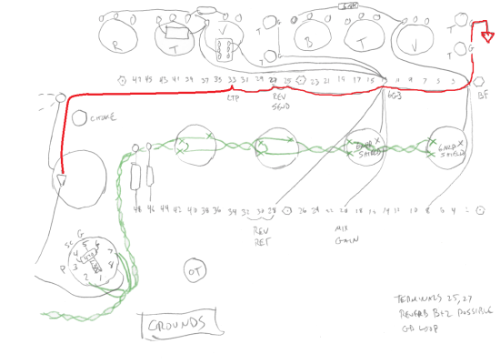
Grounding scheme with cap can?

  • Thread starter mountainhick
  • Start date
  • This site may earn a commission from merchant affiliate links like Ebay, Amazon, and others.

mountainhick

Tele-Afflicted
Joined
May 2, 2021
Posts
1,878
Location
Rocky Mountains
Building my first amp from scratch with a cap can and wondering about optimizing the ground scheme. This is PTP with terminal strips,

Since there are no individual grounds for the caps, there are also not nodes to group the grounds. Should I ground the PT center tap and the cap can to chassis, or run those to the ground buss? Seems the latter, but I am unsure because of the single ground for all nodes. Here is the layout sketch. The chain as shown does sequence in order for dropping B+ voltage. The cap can is n the left, the triangle the ground point. So ground that to the chassis or buss?

Oh, also how about the power tube grounds? attach to the cap can ground point?

ground-layout-draft.png
 

King Fan

Doctor of Teleocity
Ad Free Member
Joined
Jan 1, 2013
Posts
12,183
Location
Salt Lake City
Good questions. You're right, a cap can with a single ground defeats good grounding theory. As you'll know, if you want to ground 'right' you could lose the cap can and replace with individual filters on tag strips -- I've done that and it's elegant.

FWIW, I built my cap-can AA1164 with Rob's split grounds (shh, don't tell the priests at the temple) and ended up revising it to put the HV CT on the ground lug of the cap can, which then had a separate lead to the power amp ground. Rob and I discussed it -- he felt it might not make a difference but it couldn't hurt. Upside? It was easy. I can't say it made a difference but (priests, look away) the amp is insanely quiet with its Rob-style single preamp bus and my isolated input jacks.

1697297878884.png
 

mountainhick

Tele-Afflicted
Joined
May 2, 2021
Posts
1,878
Location
Rocky Mountains
So wh
Good questions. You're right, a cap can with a single ground defeats good grounding theory. As you'll know, if you want to ground 'right' you could lose the cap can and replace with individual filters on tag strips -- I've done that and it's elegant.

FWIW, I built my cap-can AA1164 with Rob's split grounds (shh, don't tell the priests at the temple) and ended up revising it to put the HV CT on the ground lug of the cap can, which then had a separate lead to the power amp ground. Rob and I discussed it -- he felt it might not make a difference but it couldn't hurt. Upside? It was easy. I can't say it made a difference but (priests, look away) the amp is insanely quiet with its Rob-style single preamp bus and my isolated input jacks.

View attachment 1173294
Thanks, So what about the rest, where do the power tube grounds and B+2,3,4 run? do you have a buss to the input jacks?

This the one? https://robrobinette.com/images/Guitar/AA1164/AA1164_Princeton_Reverb_Layout_DIYLC.png

Oh, and this entire project/chassis layout is possible only because of the cap can if you get my drift.
 
Last edited:

mountainhick

Tele-Afflicted
Joined
May 2, 2021
Posts
1,878
Location
Rocky Mountains
Re
DO NOT run to a ground buss that includes the pots, preamp controls, input jacks! You're asking for hum. Just ground the power section to a Transformer post or soldered nearby.
Please refer to the diagram above. Pots etc feed star points on the buss
 

Phrygian77

Poster Extraordinaire
Joined
Apr 30, 2016
Posts
7,523
Age
48
Location
Panama City, FL
Put the main secondary CT directly on the can's ground lug, then make the chassis connection from there, and don't worry about it. What you don't want to do is ground them separately to the chassis. If you had separate caps, and doing split preamp and power amp grounds, you'd want the CT going directly to the negative terminal of first filter cap, then a connection to the negative side of the screen node cap. The screen node becomes your main power amp ground point, and you make the chassis connection from there.

Lately I make a cathode ground connection from one power tube to the other with one wire back to the power amp ground, since I don't usually add 1 ohm resistors. I've also grounded the cathodes to the chassis right at the tube socket like Fender did and it doesn't make much difference.
 

mountainhick

Tele-Afflicted
Joined
May 2, 2021
Posts
1,878
Location
Rocky Mountains
Put the main secondary CT directly on the can's ground lug, then make the chassis connection from there, and don't worry about it. What you don't want to do is ground them separately to the chassis. If you had separate caps, and doing split preamp and power amp grounds, you'd want the CT going directly to the negative terminal of first filter cap, then a connection to the negative side of the screen node cap. The screen node becomes your main power amp ground point, and you make the chassis connection from there.

Lately I make a cathode ground connection from one power tube to the other with one wire back to the power amp ground, since I don't usually add 1 ohm resistors. I've also grounded the cathodes to the chassis right at the tube socket like Fender did and it doesn't make much difference.
Thanks,

So confirming, this, then run the LTP through preamp to ground at input jack?

ground-layout-draft-2.png
 

King Fan

Doctor of Teleocity
Ad Free Member
Joined
Jan 1, 2013
Posts
12,183
Location
Salt Lake City
Put the main secondary CT directly on the can's ground lug, then make the chassis connection from there, and don't worry about it.

Brilliant. I like this suggestion. As for how I did it, as you say, @mountainhick , basically like Rob. Realizing the cap can destroys your chance to either split the grounds correctly *or* collect them usefully, I just ran a single preamp bus for all the board and pot grounds. I'll repeat: it's quiet.

1697303969866.png


TBH, I can't say isolating the input jacks makes a difference. Just kinda fun. And my output tubes? Even simpler -- the 1Ω bias-measure resistors are grounded locally.

1697303787187.png


By now the priests are sharpening up their samurai swords. But look, even Merlin admits (grudgingly, but several times) that lots of amps 'get away with' this kind of ground impurity. He just says it's not best engineering. It isn't. But neither is a cap can.

R.G. Keen, who's good at both theory and the real world, says, "The star ground method is not the only way to achieve lower noise and crosstalk, it's just guaranteed to do it - that is, it's sufficient, but it may not be necessary, depending on the circumstances."
 
Last edited:

mountainhick

Tele-Afflicted
Joined
May 2, 2021
Posts
1,878
Location
Rocky Mountains
Brilliant. I like this suggestion. As for how I did it, as you say, @mountainhick , basically like Rob. Realizing the cap can destroys your chance to either split the grounds correctly *or* collect them usefully, I just ran a single preamp bus for all the board and pot grounds. I'll repeat: it's quiet.

View attachment 1173321

TBH, I can't say isolating the input jacks makes a difference. Just kinda fun. And my output tubes? Even simpler -- the 1Ω bias-measure resistors are grounded locally.

View attachment 1173320

By now the priests are sharpening up their samurai swords. But look, even Merlin admits (grudgingly, but several times) that lots of amps 'get away with' this kind of ground impurity. Is it best engineering? No. But neither is a cap can. :)

Hmm, bias resistors
 

2L man

Friend of Leo's
Joined
Nov 23, 2020
Posts
4,693
Age
65
Location
Finland
When Safety Earth was added to Mains 1970s the use of metal chassis for operative current was forbid in electric regulations. SE wire run parallel with Hot and Neutral and it make SE wire prone to electromagnetic noise.

If the Chassis (which is "an extension" of SE) is used for operative current some of the EM noise there is in HV return current will effect SE wire.

Guitar pickup signal is symmetric but instrument cable is unsymmetric, its shield is made a Signal Reference and it is connect to Chassis/SE so it is not good to build amps which increase noise to environment. Humbuckers are not too prone to absorb hum but for anyone who like single coil pickups using a single bus or separate "star" wires for all HV return current is best "grounding" method. When HV-0V is connect to Chassis only one place the HV current can not leak to Chassis when there is no path for current to return. Input jack is good place to connect Signal Reference to Chassis/SE because pre amp produce less noise than power amp.

Nowadays there are stages, studios and homes which have rich EM disturbance and then when HV0 has only one connect point to Chassis it is easy to add Ground Loop Hum Eliminator Circuit between HV0 and SE but there must be 100% verification that there is HV fuse on positive feed and that its rating is max 1/3 of GLHEC diode current rating.
 
Last edited:

Lowerleftcoast

Poster Extraordinaire
Joined
Dec 30, 2019
Posts
7,460
Location
california
Hmm. I thought we were building an AA1164 circuit but then there is a LTP. What build is this similar to? Is it push pull? Is there a schematic?
________________________________________________________________________

Just because it has a cap can doesn't mean you can't add another strategic cap or two.;)
 
Last edited:

mountainhick

Tele-Afflicted
Joined
May 2, 2021
Posts
1,878
Location
Rocky Mountains
Hmm. I thought we were building an AA1164 circuit but then there is a LTP. What build is this similar to? Is it push pull? Is there a schematic?
________________________________________________________________________

Just because it has a cap can doesn't mean you can't add another strategic cap or two.;)

AA1164 was Kingfan's interjection.

My power section is based on AB763. preamp channels, black face and 6G3, single tube reverb from mesa boogie.

I don't expect you to scrutinize all this, but here you go...

Mostly correct schematic:

sch-draft-2-png.1167198


Layout development follows this post on the build thread, https://www.tdpri.com/threads/new-p...om-design-onward.1141572/page-2#post-12188279

This is the current component layout that correlates to the following grounding diagram.

component-layout-draft-png.1173278


The ground scheme based on that layout:

ground-layout-draft-png.1173290


With power section and PT ground updated (bias supply will also ground here):

ground-layout-draft-2-png.1173304


There will be no additional filter caps.
 
Last edited:

Lowerleftcoast

Poster Extraordinaire
Joined
Dec 30, 2019
Posts
7,460
Location
california
To keep things in order, the *Rev Send* grounds should be closer to the Cap Can than the LTP ground on the bus. The OT should have a ground wire to the LTP ground.
To follow a single point ground reference scheme, the ground reference can be at/near the input jacks. Any additional ground terminal near the Cap Can should be isolated from the chassis. This will keep return current from flowing through the chassis. It will all flow through wire.

Since this circuit uses a LTP with around 70v on the cathode, an elevated heater reference is recommended. A voltage divider providing ~60v or more can be added.;)
It will double as a voltage bleed to safely bleed the filter caps.

EDIT: The 6N2P shields can be connected to the chassis rather than the ground bus. They are just shields like the metal tube covers for 12AX7 tubes we see so often.

Disclaimer: Other ground schemes can be just as quiet. The key is to keep noise from entering the gain stages.

ground-layout-draft.png
 
Last edited:

mountainhick

Tele-Afflicted
Joined
May 2, 2021
Posts
1,878
Location
Rocky Mountains
To keep things in order, the *Rev Send* grounds should be closer to the Cap Can than the LTP ground on the bus.
I did think about that being on B+2, but then thought because of the common ground at the cap can and inability to connect to a B+2 ground node, it would be moot. So, I don't get why.

The OT should have a ground wire to the LTP ground.
OK, so ground the output jack to that as well or to the chassis?

To follow a single point ground reference scheme, the ground reference can be at/near the input jacks. Any additional ground terminal near the Cap Can should be isolated from the chassis. This will keep return current from flowing through the chassis. It will all flow through wire.

Hmm, seems contrary to other input, but based on a couple of my previous grounding schemes that work fine

Since this circuit uses a LTP with around 70v on the cathode, an elevated heater reference is recommended. A voltage divider providing ~60v or more can be added.;)
It will double as a voltage bleed to safely bleed the filter caps.

Copy that.

EDIT: The 6N2P shields can be connected to the chassis rather than the ground bus. They are just shields like the metal tube covers for 12AX7 tubes we see so often.
That is good to know, will help reduce the number of wires to the star for B+4

Disclaimer: Other ground schemes can be just as quiet. The key is to keep noise from entering the gain stages.

So do I leave the center taps connected to chassis or connect to the cap can?
 

Lowerleftcoast

Poster Extraordinaire
Joined
Dec 30, 2019
Posts
7,460
Location
california
I did think about that being on B+2, but then thought because of the common ground at the cap can and inability to connect to a B+2 ground node, it would be moot. So, I don't get why.
The stronger B02 return current would share a portion of the bus with B03 LTP return current when it doesn't have to. I highly doubt a difference would be heard.
OK, so ground the output jack to that as well or to the chassis?
Theoretically yes, OT with the NFB node. In this case with the LTP ground. (I have not yet encountered trouble with just using the jack to chassis for ground. That said, I am now trying to follow the EU code for not using the chassis for return current, even the NFB.)
Hmm, seems contrary to other input, but based on a couple of my previous grounding schemes that work fine
It is hard to meet Blencowe's ideal when the input is separated like Fender amps, innit?:)
So do I leave the center taps connected to chassis or connect to the cap can?
The HT CT is always the shortest route to the reservoir cap negative to keep ripple current in a small current loop.

I recommend the heater CT elevation for this circuit.

An AC heater is not part of the DC return current. When the heater CT is not elevated, it can connect to the chassis. Essentially it is just a 0v reference so no current should flow in the CT in normal operation. A hardwired CT can use a small resistor to ground. In a fault scenario the resistor will act as a fuse, hopefully saving the PT windings. This chassis connection is usually made near the PT.
 
Last edited:

2L man

Friend of Leo's
Joined
Nov 23, 2020
Posts
4,693
Age
65
Location
Finland
I think you've posted this schematic before but would you mind posting it again?
This Vox amp has the GLHEC middle on right. This schematic has whole return current is present very well :)

However the HV fuse is installed to HV return where it does not protect enough!!! :( Actually that should make this schematic illegal! GLHEC diodes current rating must be at least three times the HV fuse rating so that there is a safety in case HV leak and there come quarantee that HV can no come to Signal Reference.

Metal Chassis always must be wired direct to mains Safety Earth because Chassis belong to Mains Primary side. Amp secondary is isolated from mains using power transformer which isolation is rated 1500V.

HV fuse must be in positive feed!!! Minimum is immediately after the tube rectifier where it burn if HV leaks.

Best HV fusing is two fuses, one on each HV AC outputs, where they protect power transformer and filter capacitors when tube rectifier shorts.

GLHEC.jpg
 
Last edited:

Scottcurry13

TDPRI Member
Joined
Nov 3, 2022
Posts
86
Location
Boston Area
I know this looks a little messy, but there is no hum and very little noise in this layout. The grounding is similar to what @King Fan mentions. This amp basically has all Rob Robinette’s mods in one amp. It’s a 5F6-A Bassman with 6V6 power tubes in a Princeton Reverb chassis.

Preamp section runs to a buss bar then to ground. Power tube section runs to a separate bar then to the same ground point. The first cap is also grounded to that point. The mains ground is on the other side of the PT. The rest of the wires are set up not to have parallel runs because parallel wires can create issues with noise.
IMG_0720.jpeg
 
Top