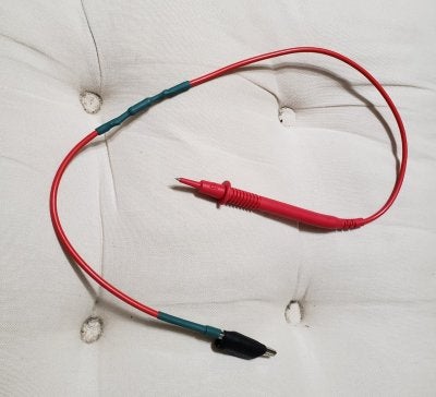
Am building a few devices in preparation for my first amp build.
Have made a light bulb current limiter and now want to make a Capacitor discharge tool.
On his site, Rob Robinette points to a simple design at this link https://www.ifixit.com/Guide/Constructing+a+Capacitor+Discharge+Tool/2177
It looks good and I have all the parts for it, but would like to go a step further in making it fool/me-proof and include a LED that indicates when the capacitor is sufficiently drained (~3V).
There is a nifty design on the Element14 site that uses a diode bridge that looks to fit the bill. I like the idea of having the connections polarity independent - one less thing to screw up.
I am unsure whether I am choosing the right components and values for an audio tube amp version of the design ( at this link -https://www.element14.com/community...235002-518418/Capacitor+Discharge+Circuit.bmp ).
R1: 2KOhm 5W resistor.
Diodes (except LED): N4002s
LED: White 5mm 20* view5500Mcd @ 20ma 3.4V typical
R2: 68Ohms ? Would this be suitable for a current limiter for the range of filter capacitor values in typical guitar tube amps ?
At least based on my simple math, the 2KOhm resistor would discharge a 40uF capacitor (I think the largest cap in a Princeton reverb) from 500V to 3V in about 0.4s.
Does this proposed implementation of the design make sense and should it be safe ?
Would prefer to get the design right before testing on a charged big filter cap.


