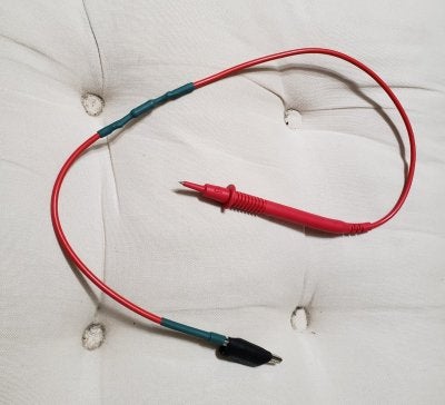
Capacitor Discharge Tool with LED - components ?

  • Thread starter pmacaula
  • Start date
  • This site may earn a commission from merchant affiliate links like Ebay, Amazon, and others.

pmacaula

Tele-Meister
Joined
Jun 2, 2019
Posts
231
Location
Toronto
Am building a few devices in preparation for my first amp build.
Have made a light bulb current limiter and now want to make a Capacitor discharge tool.

On his site, Rob Robinette points to a simple design at this link https://www.ifixit.com/Guide/Constructing+a+Capacitor+Discharge+Tool/2177

It looks good and I have all the parts for it, but would like to go a step further in making it fool/me-proof and include a LED that indicates when the capacitor is sufficiently drained (~3V).

There is a nifty design on the Element14 site that uses a diode bridge that looks to fit the bill. I like the idea of having the connections polarity independent - one less thing to screw up.

I am unsure whether I am choosing the right components and values for an audio tube amp version of the design ( at this link -https://www.element14.com/community...235002-518418/Capacitor+Discharge+Circuit.bmp ).

R1: 2KOhm 5W resistor.
Diodes (except LED): N4002s
LED: White 5mm 20* view5500Mcd @ 20ma 3.4V typical
R2: 68Ohms ? Would this be suitable for a current limiter for the range of filter capacitor values in typical guitar tube amps ?

At least based on my simple math, the 2KOhm resistor would discharge a 40uF capacitor (I think the largest cap in a Princeton reverb) from 500V to 3V in about 0.4s.

Does this proposed implementation of the design make sense and should it be safe ?
Would prefer to get the design right before testing on a charged big filter cap.
 

wabashslim

Friend of Leo's
Joined
Nov 26, 2005
Posts
4,414
Age
74
Location
Sonorous Desert
All you need to discharge the caps is a resistor with suitable extension wires and maybe clips on the ends, and the wire sure as hell doesn't need to be any bigger than 18 ga at the most. This LED gadget is major overkill for a guitar amp or anything else that's likely to found in a home. It introduces more failure points & possibilty of mistakes. Concentrate on getting your amp right in the first place.

If you have to ask - DON'T!
 

Phrygian77

Poster Extraordinaire
Joined
Apr 30, 2016
Posts
7,523
Age
48
Location
Panama City, FL
Yeah, all you need is a meter to test, and alligator clips. You can clip one end to the last power node in the circuit and the other end to ground. Done. Or, better yet, clip one of the preamp plate resistors to ground.
 

wabashslim

Friend of Leo's
Joined
Nov 26, 2005
Posts
4,414
Age
74
Location
Sonorous Desert
For that matter, when you turn the amp off the caps will discharge through the tubes in the several seconds they're cooling down, as long as you don't put it in standby (if so equipped). You can check the caps with a voltmeter to see if they're safe before reaching in there. If not, then apply the resistor.
 

kbold

Friend of Leo's
Joined
Jul 21, 2015
Posts
3,799
Location
Australia
Yeah, all you need is a meter to test, and alligator clips. You can clip one end to the last power node in the circuit and the other end to ground. Done. Or, better yet, clip one of the preamp plate resistors to ground.
Alligator clips need a suitable resistor between them.
Just a wire and you run the risk of damaging the High V caps and/or the rectifier diodes.
This then can lead to more serious/expensive damage.
 

Peegoo

Telefied
Ad Free Member
Joined
Oct 11, 2019
Posts
31,576
Location
Beast of Bourbon
A simple jumper wire with a crocodile clip on each end works fine. But me being the tool freak I am, I made one and housed it in a syringe that generously made The Ultimate Sacrifice for the greater good.

Capacitor-Discharge-Syringe.jpg


If you prefer one with a visual indicator, I recommend the Catacitor Discharge Tool. It is self-loading. When the power indicators stop blinking, the caps are dischcarged.

GIF-Catacitor-Discharge-GIF.gif
 

Paul G.

Friend of Leo's
Joined
Mar 17, 2003
Posts
4,696
Location
Rhode Island
Overthinking it.

Here's what I made.


snub2.jpg

I clip it to the chassis so I don't need two hands. Then I touch it to the last node, count to 5, move the the next to the last node, touch and count to 5, etc. until I get to the first cap, touch and hold for 10 seconds. Then I disconnect and check the voltage. Takes 1 minute and saves any worry.

Also, don't forget to unplug the AC before reaching in, you'd be shocked (get it?) to find how easy it is to brush against live AC by accident. Won't kill ya, but it stings and saves you a trip to the basement to flip the breaker back on if you touch it with your iron.
 

pmacaula

Tele-Meister
Joined
Jun 2, 2019
Posts
231
Location
Toronto
All - thanks for your feedback. Am clear most feel this tool should be a KISS device - don't complicate it.
Gus - thanks for the calculator link. The numbers line up w/ what I came up with - in .5S, a 2kOhm resistor will drain a 40mF cap from 500V to 1V or so - plenty safe.
Peegoo - nice design ! I like the syringe idea - good insulation and easy to hold. Not clear why you chose a 20K resistor over a 2K (you had one laying around ?) Are you are discharging capacitors much greater than 40mF and want to keep the max current/wattage during discharge down ?

Will likely first build the simple one w/ a 2K 5W resistor, an alligator clip at one end and some form of pointy probe at the other. May build the 'fancy' one if I have time on my hands one day.

Cheers. Patrick.
 

sds1

Friend of Leo's
Joined
May 4, 2017
Posts
3,274
Location
GA, USA
If I don't see an LED at the end of this project I'm going to be very disappointed

We should be encouraging innovation not stifling it!!

Or, better yet, clip one of the preamp plate resistors to ground.

Alligator clips need a suitable resistor between them.
If we clip directly to a preamp plate as P77 suggests in his "better yet" addendum, the plate resistor acts as a bleeder.

Just remember to unclip it before power up!
 

Phrygian77

Poster Extraordinaire
Joined
Apr 30, 2016
Posts
7,523
Age
48
Location
Panama City, FL
Alligator clips need a suitable resistor between them.
Just a wire and you run the risk of damaging the High V caps and/or the rectifier diodes.
This then can lead to more serious/expensive damage.

In most cases there's going to be little to no voltage in the caps. Unless you have fired up the amp with no tubes, or shut off the amp in standby. In the later case, there is still little to no voltage in the preamp filter caps, so clip the preamp cap to ground and let the power rail resistors do the work.

The last sentence there is why I don't do it this way anymore.

It's only a few mA. At least with a 100k plate. If it breaks something, you didn't size your resistors right to begin with.
 

James Knox

Tele-Afflicted
Joined
Aug 13, 2003
Posts
1,430
Location
Phoenix
Didn’t know about it my first amp, but I do it now on “all amps I don’t want to get bit by”.

Add a Bleeder Resistor on the first Filter Cap!
 

pmacaula

Tele-Meister
Joined
Jun 2, 2019
Posts
231
Location
Toronto
For clarity, I have most of the parts for both the basic and 'fancy' versions (see photos).
Just need to go out to the shed an get a bit of multi-stranded wire (vs the solid 12AWG stuff in the photo).

Before posting last night, I breadboarded the fancy circuit (+/- rails would be where ground and the capacitor to be drained would connect). Will probably let it sit (unless I need the breadboard for something else) for now & proceed w/ the basic one.
If anyone does have thoughts on an appropriate value for the current limiting resistor (R2) for the LED, would appreciate the input.

Cheers. Patrick.

y4mlWvSVKYT7p5hNiXU_RI4JzJNHX6ISsZ4Isnw0OxS4tEc1rl5ZLjcVf1Vn28oqJW5QrXoaqoAP6O5fcR6AIvxKAXbGIEvxFxjUcW8wDNuz0xAg9wRGyEDIprSBp6VP0DzA9TFNlAsgPL0gU5fUXb-8v7QEiJq8eZ_mDGWi9wYdSHTH49lqmJT8AGDRLuv67Ay

y4mXOy8Imv2TpTgJVetg0zf0TbanEUnHbXmUThSels3HYLCI-4SyddIabSnsFnVsPH7x9-y9VSZOTiXV_Umex0pWyIQ_fO2JRdB6d87BS4FPDXcuXdc7OVl5MfLtTVblDVp1gSoNk9j3ds9xC4GHb_8Y6j2DvEj0WU4LqJrpaFDD4xDSNN2Ed4jbN9BYJYRf8x_
 

sds1

Friend of Leo's
Joined
May 4, 2017
Posts
3,274
Location
GA, USA
Add a Bleeder Resistor on the first Filter Cap!
An optimization is to put one on the last filter cap as well. Or anywhere on the other side of the standby switch really. And I guess it would depend on the amp, but point being you want bleeders on both sides of standby when caps are present on both sides of standby. Otherwise the standby switch will prevent bleeding on the preamp side.
 

pmacaula

Tele-Meister
Joined
Jun 2, 2019
Posts
231
Location
Toronto
Peegoo - By fancy, I meant the design with the diode bridge and LED vs the basic bleeder resistor and probe only design.
 
Top