Passive and super simple attenuator for cutting 4-5db?

  • Thread starter klobasa
  • Start date
  • This site may earn a commission from merchant affiliate links like Ebay, Amazon, and others.

klobasa

Tele-Holic
Joined
Jul 20, 2011
Posts
700
Location
Europe
I have tried everything between master volumes, traditional attenuators and different speakers and came to the conclusion that I need and want a very passive attenuator with my 8 Ohm speaker to cut somewhere between 4-5db.

With 4 Ohm and/or 8 Ohm resistor I can cut 3db or 6 db and still have the correct 8 Ohm reading (I have the same speaker in 8 and 16 Ohms), but what kind of resistor setup would give attenuation somewhere between 4-5db? That is the sweet spot. I have measured this multiple times with db meter and with an attenuator that I had.

I will not use any kind of switches or adjustments in the setup. Not even bypass.

Thanks in advance!

PS: I do not want an adjustable attenuator...
 

Lupo

Tele-Holic
Joined
May 19, 2014
Posts
770
Location
Genova-Italy
If I did not make a mistake in my calclulation (I have no paper and pencil now) with an 8 ohm.speaker you should get -5dB using an L-pad with 3.2 ohm in series and 12 ohm in parallel to the speaker. To get -4dB you need 14 ohm in parallel and 2.9 in series.
 

King Fan

Doctor of Teleocity
Ad Free Member
Joined
Jan 1, 2013
Posts
12,183
Location
Salt Lake City
For L-pad with equal impedance above and below, this site gives the math and works an example to attenuate 6dB.

But something basic I don't know -- do we want to attenuate our dB in terms of voltage or in terms of power? The equations are different...
 

klobasa

Tele-Holic
Joined
Jul 20, 2011
Posts
700
Location
Europe
If I did not make a mistake in my calclulation (I have no paper and pencil now) with an 8 ohm.speaker you should get -5dB using an L-pad with 3.2 ohm in series and 12 ohm in parallel to the speaker. To get -4dB you need 14 ohm in parallel and 2.9 in series.

Can this be done with power resistors instead of l-pads?
 

King Fan

Doctor of Teleocity
Ad Free Member
Joined
Jan 1, 2013
Posts
12,183
Location
Salt Lake City
Yep... put your numbers in to this and it'll work it out for you and show you the simple circuit and the minimum power handling necessary for the two resistors.

Thanks. That calculator is a *ton* simpler than trying to figure out anti-logs. :)

Sadly, it still doesn't sort out my ignorance of how electronics affects acoustics. I notice it attenuates dB of power. Can we take it that dB of power = dB of SPL?

And it looks like this is still an L-pad. Does an L-pad differ from "power resistors"?
 

dan40

Friend of Leo's
Joined
Aug 19, 2015
Posts
3,868
Location
Richmond Va
I have never liked the couple of attenuators that I tried but a few months ago I came across this thread...http://www.marshallforum.com/threads/simple-attenuators-design-and-testing.98285/ and I decided to build the circuit shown on page 3 for an 8 ohm speaker. I must say that I am really enjoying this with my Princeton and 50 watt Marshall style build. I notice very little tone change other than the effect of the lowered volume at the speaker. It does include a couple switches but it was a very easy build if you want to try it.
 

AAT65

Doctor of Teleocity
Joined
May 29, 2016
Posts
10,008
Location
Edinburgh, Scotland
For L-pad with equal impedance above and below, this site gives the math and works an example to attenuate 6dB.

But something basic I don't know -- do we want to attenuate our dB in terms of voltage or in terms of power? The equations are different...
The equations are different so that answer is the same, if you know what I mean... because power is related to the square of voltage, you need a different equation. 10dB voltage reduction (reduce by a factor of 3.16) gives a 10dB power reduction (reduce by a factor of 3.16x3.16 = 10).
6dB in voltage is halving (50% reduction), 6dB in power is quartering (75% reduction).
 

King Fan

Doctor of Teleocity
Ad Free Member
Joined
Jan 1, 2013
Posts
12,183
Location
Salt Lake City
The equations are different so that answer is the same, if you know what I mean... because power is related to the square of voltage, you need a different equation. 10dB voltage reduction (reduce by a factor of 3.16) gives a 10dB power reduction (reduce by a factor of 3.16x3.16 = 10).
6dB in voltage is halving (50% reduction), 6dB in power is quartering (75% reduction).

I wasn't clear enough about what puzzled me (many things do). :D

I see that both equations have to end up the same place. (Your explanation of why *is* extremely helpful, and I appreciate it.)

But when we talk SPL or *perceived loudness*, do the acoustic dBs we're talking about relate to power dBs (I thought) or to voltage dBs?
 

AAT65

Doctor of Teleocity
Joined
May 29, 2016
Posts
10,008
Location
Edinburgh, Scotland
I wasn't clear enough about what puzzled me (many things do). :D

I see that both equations have to end up the same place. (Your explanation of why *is* extremely helpful, and I appreciate it.)

But when we talk SPL or *perceived loudness*, do the acoustic dBs we're talking about relate to power dBs (I thought) or to voltage dBs?
Well, I think it’s not quite as simple as “3dB more power = 3dB higher SPL/Loudness”: but looking at the power or voltage increase as a guide to the SPL increase won’t be a million miles off.
The reasons it’s not total simple is because the efficiency and linearity of the speaker(s) comes into play, and the assumed frequency sensitivity of the human ear (modelled usually by A or C-weighting to give La or Lc loudness readings). In particular as levels increase the sensitivity of the ear to different frequencies varies, IIRC, and speaker and amplifier linearity may have a significant effect.
So if 6.25W of power gives an Lc of 80dB then 12.5W of power (100% power increase = +3dB) will give an Lc of roughly 83dB.
You can also think of it as increasing the signal from 10V to 14.1V into a 16ohm load (41% voltage increase also = +3dB), same thing applies, 3dB more Volts gives roughly 3dB more SPL.
 

Silverface

Doctor of Teleocity
Ad Free Member
Joined
Mar 2, 2003
Posts
10,518
Age
73
Location
Lawndale CA
Things like this are never very simple.

To add to the fun, a resistor is static; a speaker's impedance is dynamic and changes depending on the frequencies fed to it. An "8 ohm" speaker means 8 ohm impedance at a fixed test frequency - not during actual use. So resistor-based attenuators can't be relied on to provide you with a reduction in SPL or output that you can calculate. You can only roughly estimate those numbers. An attenuator based on an actual speaker voice coil works more like a speaker (i.e. Weber's MASS) - but you just use math to determine the reduction (you need an RMS meter, calculator and oscilloscope and decide what is the acceptable amount of total harmonic distortion - at minimum).

There's no very practical way to set a loudness reduction target in DB (or SPL) and "calculate" a fixed resistor value that will get you there. You must have a target THD content and the equipment to measure it (you can't simply listen - that causes wide variations) and there are audio engineering details involved. There's a "speakers vs ohms" thread in (I think) Amp Central Station that has been discussing very similar tech details for days.
 

klobasa

Tele-Holic
Joined
Jul 20, 2011
Posts
700
Location
Europe
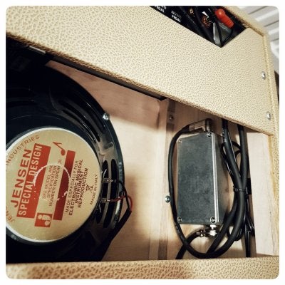
Well, here it is. Based on the calculator, 4,5db attenuator with minimal settings. Works very well.
 

Attachments

  • 20180913_224728-01.jpeg
    20180913_224728-01.jpeg
    272.2 KB · Views: 159

King Fan

Doctor of Teleocity
Ad Free Member
Joined
Jan 1, 2013
Posts
12,183
Location
Salt Lake City
Well, here it is. Based on the calculator, 4,5db attenuator with minimal settings. Works very well.

Good stuff. Very clean install -- I like it. Can you share a layout or schematic of the values you ended up with?
 

klobasa

Tele-Holic
Joined
Jul 20, 2011
Posts
700
Location
Europe
Good stuff. Very clean install -- I like it. Can you share a layout or schematic of the values you ended up with?

Thanks :)

With that calculator, I checked the values for 4db and 5db cut and saw that local electronic parts store had values that fall right between those. 3.3 Ohm and 12 Ohm resistors, couple of switchcraft jacks and a pedal enclosure. Very easy and simple setup.

I don't hear any loss in treble or anything negative change in sound either.
 

Attachments

  • Screenshot_20180910-080359_Firefox.jpg
    Screenshot_20180910-080359_Firefox.jpg
    42.4 KB · Views: 477

gusfinley

Tele-Afflicted
Joined
Jun 11, 2014
Posts
1,765
Location
SLC, UT
Thanks :)

With that calculator, I checked the values for 4db and 5db cut and saw that local electronic parts store had values that fall right between those. 3.3 Ohm and 12 Ohm resistors, couple of switchcraft jacks and a pedal enclosure. Very easy and simple setup.

I don't hear any loss in treble or anything negative change in sound either.

It doesn't get any simpler than that!
 

johnDH

Tele-Meister
Joined
Jun 24, 2016
Posts
483
Age
65
Location
Wilton NSW
I have never liked the couple of attenuators that I tried but a few months ago I came across this thread...http://www.marshallforum.com/threads/simple-attenuators-design-and-testing.98285/ and I decided to build the circuit shown on page 3 for an 8 ohm speaker. I must say that I am really enjoying this with my Princeton and 50 watt Marshall style build. I notice very little tone change other than the effect of the lowered volume at the speaker. It does include a couple switches but it was a very easy build if you want to try it.

Hi, thats my post! Im glad you like it!
John
 
Top