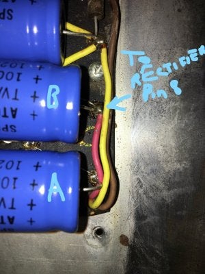
Is this filter cap backwards?

  • Thread starter Jariggs
  • Start date
  • This site may earn a commission from merchant affiliate links like Ebay, Amazon, and others.

Jariggs

TDPRI Member
Joined
Aug 4, 2015
Posts
15
Location
Hyattsville, MD
Hi. I took the chassis out of my my early 70s Pro Reverb to add a bias adjust pot. When opened up the doghouse to verify no voltage was in the capacitors, I noticed that one of the filter caps seemed backwards based upon what I have seen in other silverface fenders. In other amps, the capacitor in the far left in this picture is usually laid out in the opposite polarity from all the other capacitors. There is continuity to ground for on the positive end of that capacitor. IMG_4684.JPG

I've had the amp over a year now, and while it worked it has always been a little noisy. Maybe this is why? I am pretty sure of the answer, just a little new to working on amps and would appreciate opinions/validation. Thanks!
 

FenderLover

Poster Extraordinaire
Joined
Jun 11, 2009
Posts
7,073
Location
Minnesota
It is backwards compared to the layout. Someone may have rewired it, but if (+) measures continuity to ground, I'd look into it.
 

Jariggs

TDPRI Member
Joined
Aug 4, 2015
Posts
15
Location
Hyattsville, MD
Thanks. I'll trace the wiring in a little bit based on those schematics. Assuming it is misconfigured, could running the capacitors like that cause them damage?
 

Jariggs

TDPRI Member
Joined
Aug 4, 2015
Posts
15
Location
Hyattsville, MD
Doctorx33, that what I would have thought too,

I traced the wiring and there is continuity between pin 8 on the rectifier tube socket and (+) of the capacitor furthest from the edge of the board (labeled B in the pics below).

Maybe since there are two capacitors and both are slightly over spec (100uf vs 70uf) that the first capacitor in line (B) was handling the filtering? There are also the two 220k resistors in there spanning the positive and negative ends of each capacitor, which jibes with the schematic.

InkedIMG_4686_LI (2).jpg InkedIMG_4685_LI.jpg

Any more input would be appreciated. Thanks.

(Sorry about the bad handwriting -- I've never been good at writing with a mouse.)
 

peteb

Poster Extraordinaire
Joined
Apr 25, 2003
Posts
7,406
Location
Cascadia
If the cap is wired backwards you'd have bigger problems than xtra noise.


I agree and I disagree. I have never seen a filter cap put in backwards, so I am not familiar with what to expect.

Caps function either way. All they are is lead, foil, paste, foil, paste, foil, lead. Backwards it's the same thing. The difference is one end, the lead is connected to the outer cover. This is known to pick up noise. The major problem is the outside cover is at an elevated voltage and can short out to ground. But you can see the caps in the picture are covered in the blue insulating material, which could prevent the short.

So theoretically the filter cap could work backwards.


I could be wrong, please correct me if I am wrong.
 

Wally

Telefied
Ad Free Member
Joined
Mar 17, 2003
Posts
46,337
Location
Lubbock, TX
there is a reason there are + and - ends for electrolytic caps.
In this circuit, those two caps are wired in series so as to provide the voltage capacity for the amp. This amp may have been reworked so as to provide that series connection with both caps oriented as seen above rather than as it left the factory with the + end of the first cap away from us on the pic. I would lift the negative ends of the caps and check the connections between the eyelets and those resistors.
If the caps are in parallel, then you have a 200 mfd cap with only 350VDc of handling capability.....they might not last long.
 

2 Headed Goat

Friend of Leo's
Joined
Jul 28, 2012
Posts
2,248
Location
age 8
The far end capacitor being reverse to the others is correct in some Fender amps.
IIRC this is mentioned in Gerald Weber's and or Aspen Pittman's book (I believe its the former) I know it seems quirky to see the cap on the far left opposite to the others but it is deliberate. FYI, an electrolytic capacitor installed backwards will generally explode as soon as power is applied.
 
Last edited:

Jariggs

TDPRI Member
Joined
Aug 4, 2015
Posts
15
Location
Hyattsville, MD
Thanks. Wally, from what I can tell those caps are in series, but I probably will lift the ends to get a better look and test the connectivity. The rest of the amp looks pretty stock, wiring-wise, but I haven't compared directly to the schematic yet.
 

Wally

Telefied
Ad Free Member
Joined
Mar 17, 2003
Posts
46,337
Location
Lubbock, TX
The far end capacitor being reverse to the others is correct in some Fender amps.
IIRC this is mentioned in Gerald Weber's and or Aspen Pittman's book (I believe its the former) I know it seems quirky to see the cap on the far left opposite to the others but it is deliberate. FYI, an electrolytic capacitor installed backwards will generally explode as soon as power is applied.

IT seems that somewhere in my memory I may have read about these 'exceptions to the rule' regarding the orientation of that cap.
As I view this picture, am suspecting that these two caps are miswired. The two negatives are tied together.
image removed


IN this picture...
image removed


We see no connection to the first eyelet on the positive end there except for the cap. Even if there is a connection under the board from this eyelet to the second cap's negative connection,
doesn't that connection between the two 'negative' eyelets in the first picture present a problem IF a circuit were supposed to be two caps in series?
I am thinking that this amp is running on one first stage cap....a 100mfd/350VDC cap that is not going to live long with the voltages that are being presented to it. The first cap may in fact not be
presented with voltage at all.
IF I am incorrect, then I would really like to know exactly how it is wired up. I don't see those two caps being correctly wired from what I can see from here.
 

peteb

Poster Extraordinaire
Joined
Apr 25, 2003
Posts
7,406
Location
Cascadia
A connectivity test is in order.


Two caps in series is a total waste of capacitance, 70+70=35, but the benefit is even though the capacitance drops, the voltage ratings are additive, 350 + 350 = 700

Fender did it both ways but series became favored for the high voltage rating, and it's called the totem pole arrangement. It's one of the differences between aa763 vs ab763, they went from parallel to series.
 
Last edited:

2 Headed Goat

Friend of Leo's
Joined
Jul 28, 2012
Posts
2,248
Location
age 8
I don't recall the reason for the last cap being reversed tho I think it may be to decrease the value of the other capacitor to obtain a lower value.
I was a bench tech in a former life (not working specifically on tube amps)
Unlike resistors, with capacitors wiring them in series (- to +) decreases the capacitance and wiring them in parallel (- to -. + to +) increases it.

I believe your amp is wired correctly. IMO, unless you have been experiencing issues with your amp, I would leave it as it is.
 
Last edited:

peteb

Poster Extraordinaire
Joined
Apr 25, 2003
Posts
7,406
Location
Cascadia
there is a reason there are + and - ends for electrolytic caps.


Isn't the difference that one lead, the negative one, is connected to the metal cover? But otherwise the same and they can function in reverse.

The idea is you want the outer cover at the lower voltage, preferably ground.


In series, the more elevated cap has its outer metal cover at an elevated voltage, not good, but true. The voltage on the outer cover of the elevated cap(the negative end) would roughly be half of the b+ voltage on the other end of the same cap(the positive end)
 
Last edited:

Wally

Telefied
Ad Free Member
Joined
Mar 17, 2003
Posts
46,337
Location
Lubbock, TX
Yes, Fender used two caps in parallel to double the capacitance. When the amp design for the bigger amps moved to PT's that yielded higher B+, there was a need for a higher voltage capacitor in that first stage. So, they used two caps in series in order to double the voltage capacity, There is no 'waste' of anything. These days we can buy 600VDC electrolytics that are not very large. I have a 600VDC cap that I pulled of an old Fender.....it was too big to fit under the doghouse, but its voltage rating was much more appropriate for the amp.
Old goat....I am just trying to understand. How can we think that these two caps are wired in series as the schematic calls for...and which the voltage in the circuit demands....when we see the two negative ends of those two caps tied together? I don't think the filter section is correctly wired. I suspect that the first cap is sitting there doing nothing in effect.
IF these two caps were to be in series wiring, the red wire would need to contact the positive end of one of the caps. The negative end of that cap would then have to contact the positive end of the other cap in the pair...with the negative of that cap going to ground. The negative of both of these caps is at ground. And....I suspect that the positive end of the first cap is connected to nothing more than one end of a 220K resistor which then goes to ground. So....that first cap is at ground o n both ends....and the second cap is at risk due to the voltage demands.
With the amp on a bench, it would not take long at all to ascertain what is going on there. IF my analysis is correct, one could lift that positive connection of the first cap and the amp will continue to operate as it has been....incorrectly in more than one way. First, the voltage is going to overwhelm the cap at some point, and secondly, the capacitance is too high for the rectifier tube.

I am ready to learn if my thinking is not on track here....but it just doesn't look correct from here.
 

2 Headed Goat

Friend of Leo's
Joined
Jul 28, 2012
Posts
2,248
Location
age 8
Yeah Wally, you may in fact be right re it being wired incorrectly… IIRC there can connections on the underside of the fibre board. Agreed, putting the amp on a bench or having a qualified tech take a look should solve things… I'm of the mindset tho to leave it as is unless there's some issue with how the amp performs.
 

Wally

Telefied
Ad Free Member
Joined
Mar 17, 2003
Posts
46,337
Location
Lubbock, TX
Pete, as noted above.....if an electrolytic is hooked up backwards, it will fail in short order. A small 25mfd/25VDC cap will sound like a .22 caliber long rifle going off when it goes. A larger cap will sound like a shotgun.

If we look at the schematic above to see the series connections and then look at that wire connecting the two negative ends of the first two caps, we can know very quickly that this amp is not wired to the schematic's design. These two caps could be oriented in this manner....both positives next to each other physically and the negatives at the other end together. But...the negatives would not be tied together with that bare wire. The negative end of that cap that has the red wire on the positive pole would connect with the positive of the first cap and the negative of the first cap would go to ground.
Until convinced otherwise, I am going to think that the first cap is 'for looks only' being wired as it is....and the second cap is tasked beyond its specifications....and holding up for the time being.
 

peteb

Poster Extraordinaire
Joined
Apr 25, 2003
Posts
7,406
Location
Cascadia
Thanks Wally.

There is no 'waste' of anything.

What I mean is in series two 70 mF capacitors combine to make 35 mF. So they put in 140 mF of capacitors, and they only get 35 mF out of it. I am calling that a loss or a waste of capacitance. Two 70s are going to take up more space than one 35 as well. Combing caps in series is like combining resistors in parallel, which is not done as it is a bad design practice.
 

Jariggs

TDPRI Member
Joined
Aug 4, 2015
Posts
15
Location
Hyattsville, MD
Thanks everyone! I'll do a deeper dive on the existing circuit when I can and report back (maybe tomorrow -- silly kids needing parenting and stuff:)).

I did find this site which seems to have the caps both in the same direction on a 69 PR (mine is a 74). (link removed)
 

peteb

Poster Extraordinaire
Joined
Apr 25, 2003
Posts
7,406
Location
Cascadia
Thanks again Wally,

if an electrolytic is hooked up backwards, it will fail in short orde

Why does that happen?

The aa763 pro uses two 20s in parallel for 40, the ab763 pro uses two 70s in series for 35.

So just by looking at the values of the caps you should be able to see if they are supposed to be connected in series or parallel.
 
Last edited:
Top