
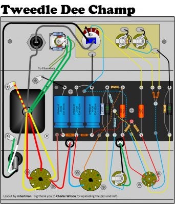
Hi. I have been building a Dumble Tweedle Dee Champ amp. Now finished it makes no sound, except scratch sounds on the preamp/PT tubes, and a very low noise when touching the jack tip.
I get voltage on all parts that should have and I have changed the filter caps, many of the resistors, looked closely on the input jacks and changed the tubes.
The OT wires I have connected the 0v to the 6v6 tube and the 8k to the rectifier. I have connected the 5v and 0v to the rectifier.
This looks like a straight forward build, so I am a bit puzzled?
Any immediate ideas on what to look for next?
")

