Aoxomoxoa710
TDPRI Member
Hello. I'm new in the group. Can someone help me with my twin reverb 135w ultralinear?
The output transformer has broken.
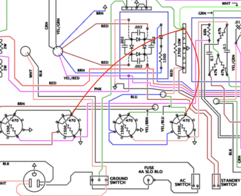
I have an output transformer from an older twin reverb. Exactly a 022889. It is not an ultralinear output transformer. It does not have 4 wires that go to the power tubes. It only has two wires. I have put this output transformer in the amplifier and it seems to work perfectly. My question is. Do I have to modify something in the circuit of my amplifier. Change some value or add some resistance? Any information is appreciated.Thanks.
The output transformer has broken.
I have an output transformer from an older twin reverb. Exactly a 022889. It is not an ultralinear output transformer. It does not have 4 wires that go to the power tubes. It only has two wires. I have put this output transformer in the amplifier and it seems to work perfectly. My question is. Do I have to modify something in the circuit of my amplifier. Change some value or add some resistance? Any information is appreciated.Thanks.