GotA24Fretter
Tele-Holic
You can also fit a LarMar very easy in the ground hole. Then you can crank and not get a visit from an angry neighbor that doesn't appreciate involuntary live streaming your performance into their home.

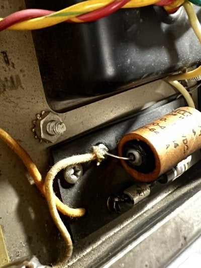
Change the cathode caps sooner than later. I've had some fail in such a way as they test as diodes on an M Tester unit. This would be mostly unnoticed as far as function because diodes can be used to bias a triode, but the bias will be shifted from the intended point. This can result in less/more gain from a stage and a noticable change in overall sound of the amp. A cathode cap that fails open will cause a roughly 6dB drop in gain across the board. Don't be surprised if you find your amp sounds louder and fuller (ie. As intended) once you perform this maintenance. And don't sweat if you can't find a 25μF cap. Anything larger than about 10μF will be sonically indistinguishable, as it fully bypasses all guitar frequencies. So the readily available 22μF is just fine.
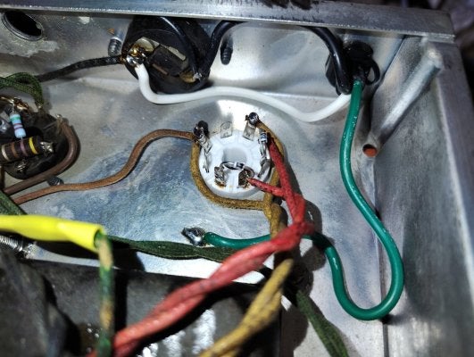
As for the 100 ohm artificial center tap, you may hear a slight difference in hum between the two arrangements, especially if the filament CT isn't perfectly balanced, or the tolerance of the resistors used are wide. It's hard to say which would be quieter in your specific application. This is why hum balance pots exist.
Also, seeing this photo again reminded me of 3kV diodes from plate to ground. This is also cheap insurance for the output transformer if you're averse to adding MOVs. It's added to the socket, so easy to do while replacing plate and screen resistors. It adds a negligible amount capacitance to the plate, so it's sonically invisible--but it may add some stability to the power amp section if it is on the verge of ultrasonic oscillation. R3000s are a popular choice for this.
Change the cathode caps sooner than later. I've had some fail in such a way as they test as diodes on an M Tester unit. This would be mostly unnoticed as far as function because diodes can be used to bias a triode, but the bias will be shifted from the intended point. This can result in less/more gain from a stage and a noticable change in overall sound of the amp. A cathode cap that fails open will cause a roughly 6dB drop in gain across the board. Don't be surprised if you find your amp sounds louder and fuller (ie. As intended) once you perform this maintenance. And don't sweat if you can't find a 25μF cap. Anything larger than about 10μF will be sonically indistinguishable, as it fully bypasses all guitar frequencies. So the readily available 22μF is just fine.
As for the 100 ohm artificial center tap, you may hear a slight difference in hum between the two arrangements, especially if the filament CT isn't perfectly balanced, or the tolerance of the resistors used are wide. It's hard to say which would be quieter in your specific application. This is why hum balance pots exist.
Also, seeing this photo again reminded me of 3kV diodes from plate to ground. This is also cheap insurance for the output transformer if you're averse to adding MOVs. It's added to the socket, so easy to do while replacing plate and screen resistors. It adds a negligible amount capacitance to the plate, so it's sonically invisible--but it may add some stability to the power amp section if it is on the verge of ultrasonic oscillation. R3000s are a popular choice for this.
Last edited:


") . One follow up question, is there any guidance on "when" I should do this. The amp sounds great so should I let it ride? Or are they ticking time bombs and the sooner they are replaced the better?
. One follow up question, is there any guidance on "when" I should do this. The amp sounds great so should I let it ride? Or are they ticking time bombs and the sooner they are replaced the better?