Tremolux 64 Work Order

  • Thread starter jaonline
  • Start date
  • This site may earn a commission from merchant affiliate links like Ebay, Amazon, and others.

jaonline

TDPRI Member
Joined
Jul 25, 2025
Posts
16
Location
Seattle
Hello Friends.

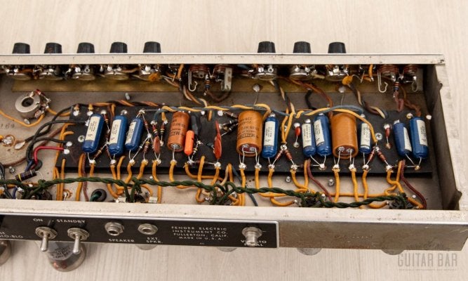
For my first post at this forum I present a 1964 Fender Tremolux amp. I recently acquired this amp. It sounds great, fully functional and appears to be mostly original.
IMG_2192.JPG

My goals with the amp are (in order of importance) 1. Maintain amp's character sound and playability. 2. Eliminate items dangerous to me. 3. Mitigate items that may damage vintage, difficult to replace amp components. 4.While I don't want a museum piece, avoid significantly devaluing amp.

So I fell like I am starting at a good place with this amp, but there is some work that needs to be done. I would like to do some of this work myself but also feel like some work is better done by an amp tech with all the right tools.

I am looking for folk's advice on if this list looks good or if I am missing something. So here goes:

1. Three prong cord was installed with a tight ground wire to the transformer lug (see photo IMG_2203). I believe a longer ground wire to a chassis solder is considered a a better installation. Cord is too short at about five feet. - Amp Tech would need to do this.

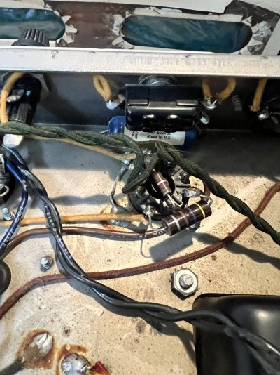
2. Death cap, ground lift switch and convenance outlet are all still in place and wired (see photo IMG_2202). I would like these components lifted from the circuit but left in place. I may in the future use the switch and the outlet hole for future mods. - Amp Tech should do this.

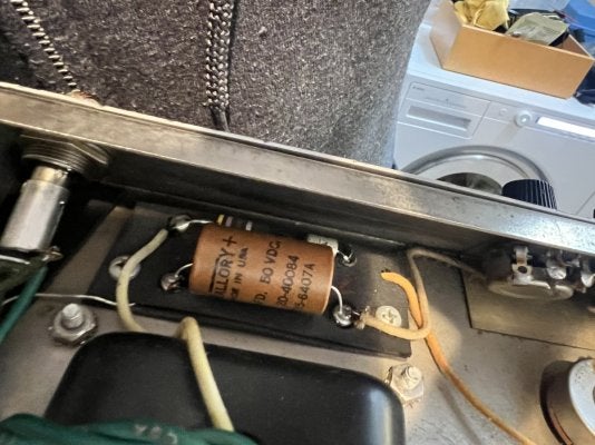
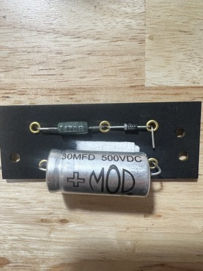
3. Bias Board - The original cap is still intact (IMG_2200). I am assuming the resister and diode are original too. I have built a brand new bias board (IMG_2247) from all new parts and plan to swap out the new board for the old one. - As long as I can reuse the ground wire coming from the chassis I would do the change myself.

4. I see several folks lift the the center tap for the power trans. secondary heater wires and install a pair of 100ohm resistors. I would do this when I replace the bias board.

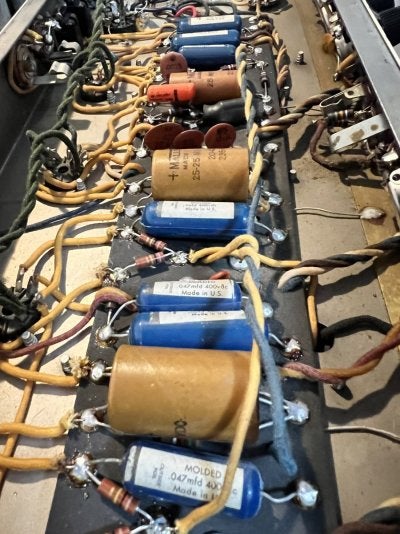
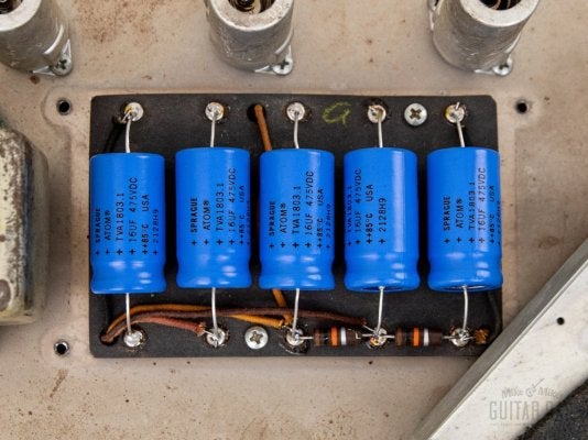
5. Electrolytic Caps - The filter caps have all been replaced but the remaining electrolytic caps (Mallory) are all in place. If necessary, I would do this work.

I am attaching photos below in case anyone would be so kind to look and see if they notice any other items that should be added to the list. I will likely finish building a Mojotone Tweed Princeton before taking the T-lux to the tech for items 1 and 2. That way I still have an amp to play with and I gain experience building the new amp. Then I would tackle the rest of the list.

Thank you in advance for your help and insights.
 

Attachments

  • IMG_2198.JPG
    IMG_2198.JPG
    251 KB · Views: 46
  • IMG_2200.JPG
    IMG_2200.JPG
    209.2 KB · Views: 47
  • IMG_2202.JPG
    IMG_2202.JPG
    232.5 KB · Views: 47
  • IMG_2203.JPG
    IMG_2203.JPG
    219.1 KB · Views: 48
  • IMG_2211.JPG
    IMG_2211.JPG
    270.8 KB · Views: 50
  • IMG_2247.JPG
    IMG_2247.JPG
    212.9 KB · Views: 46
  • Chassis Gut Shot 2.jpeg
    Chassis Gut Shot 2.jpeg
    186.1 KB · Views: 46
  • Chassis Power Caps.jpeg
    Chassis Power Caps.jpeg
    210.3 KB · Views: 50

sds1

Friend of Leo's
Joined
May 4, 2017
Posts
3,274
Location
GA, USA
In accordance with your stated goals you are doing way too much IMO.

1) seems unnecessary at this point
2) lift the death cap but leave everything else alone
3) why not just recap and let it be?
4) no
5) sounds great, do this one

Also, welcome! 🤘🏻
 

jaonline

TDPRI Member
Joined
Jul 25, 2025
Posts
16
Location
Seattle
In accordance with your stated goals you are doing way too much IMO.

1) seems unnecessary at this point
2) lift the death cap but leave everything else alone
3) why not just recap and let it be?
4) no
5) sounds great, do this one

Also, welcome! 🤘🏻
Thank you. Appreciate the clear guidance. 🤘🏻
 

King Fan

Doctor of Teleocity
Ad Free Member
Joined
Jan 1, 2013
Posts
12,183
Location
Salt Lake City
Cool amp, and clear, well-ordered questions.

I totally agree with @sds1. And if you take his advice, do you really need a tech to clip out the death cap? (Do save the cap -- the blue 'Ajax' usually work fine, in fact are highly desireable.)
 

Jasonpatrick

Friend of Leo's
Joined
May 29, 2022
Posts
2,203
Age
46
Location
Portland Oregon
Are you going on tour with it? Is it getting hauled out to gigs every night? Is it working? Sound great? Then leave it alone. Clip out the death cap if you must but it honestly ain’t necessary. You can also just bypass it as well. Couple wires and yer done. Them blue mallorys ain’t that old.
 

GotA24Fretter

Tele-Holic
Joined
Jan 3, 2024
Posts
879
Age
38
Location
TX
I'm very much a "if you're gonna do work on it, you might as well do it right/completely" guy. I'm for redoing the 3 prong correctly with a proper chassis ground.

Replace the cathode bypass caps. You can strategically tweak values to reduce background noise or gain better performance. Specifically, a 250μF cap (available from MOD) would be very helpful with the tremolo oscillator stage. It would also be useful to fit one of these to the first gain stage of each channel (reduces h-K leakage early in the preamp). The driver stage of the tremolo circuit should have a reduced cap value. MOD has an 8μF value that I use here for visual compatibility if I've used them everywhere else. The schematic value is 5μF (4.7μF is the modern value) on some models. This improves speed control tracking.

I'm for lifting the filament center tap and replacing with an artificial CT. You can even use 1/3W fusible resistors for added protection. To really put a shine on it, you can elevate the artificial center tap easily at the bias board. See my thread here (post 16 specifically): https://el34world.com/Forum/index.php?topic=30961.msg362664#msg362664date=1744759965.

To protect irreplaceable original transformers you can fit an HT fuse, MOVs across the OT primaries, and backup diodes on the rectifier tube. See RG Keen's "Immortal Amp Mods".

Replace the screen resistors and grid resistors on the power tube sockets. You don't want to lose bias or have potential lost power due to intermittent screen resistors.

Also, I noticed the V1&2 plate resistors have been replaced (along with the PI bias resistor). The amp may have a background noise problem the last person who was in there was chasing. So be aware of that. It may have board leakage, or some other contributors to a high noise floor.

Vintage Fender jacks tend to break the solder joint that connects them. Reflowing this joint is cheap insurance. Also, the cloth wire from these to the tube grids tend to get noisy over time. Fender later used shielded coax here. I think that was an upgrade from the blackface days, personally.

Finally, the cap across the 10M resistor at the tremolo roach is an outdated mod. Fender's later fix is to have that span across the roach to ground. It also means there's was tremolo related noise at one point, so keep an ear out for if that's still happening. There are other tricks that can be tried to reduce the noise.
 

King Fan

Doctor of Teleocity
Ad Free Member
Joined
Jan 1, 2013
Posts
12,183
Location
Salt Lake City
Heh, it was bound to happen. This is TDPRI; smart opinions are gonna vary. So now we span pretty much the whole spectrum from "Let It Be" to "Any Job Worth Doing...." Good! *you* get to choose how to balance your goals of originality v. durability.

There *are* a very few 'amp influencers' who recommend updating *nothing* as long as the amp works, but all the experts I trust find that's too extreme. (As a detail, @Jasonpatrick , he said he was gonna replace the never-reliable cardboard Mallory e-caps, not the nice blue ones.)

And yes, the 'make it totally safe' approach might indeed protect your amp over time. (IIRC R.G. Keen's 'immortal amp mods' were a series of increasingly complex articles in PremierGuitar?) But taken all together, they're complex and 'invasive' in the sense the amp ain't gonna look vintage-y any more. Will that enhance its value to a future player? Or decrease it to a future collector? Personally, I'd be more inclined to do these on a new build, not retrofit them to a vintage amp. But you could pick and choose the most useful and least invasive. IIRC, Keen's first step was backup diodes on the rectifier -- not very invasive. And, as @24-fretter notes, it's super logical to replace the important resistors that sit baking over the tube sockets with modern, high-wattage, heat-resistant versions. You get to decide.

Me, I like a good compromise. Here's just one example: The safety earth ground is indeed super important (and BTW 'solder to chassis' was considered solid in the '60s -- we now require a dedicated bolted anchor.) If drilling a new hole in a vintage amp didn't appeal, you could at least make sure the PT bolt anchor is 100% bombproof -- massively crimped ring terminal, star washer under, Keps nut over, drop of Loctite, etc.
 

King Fan

Doctor of Teleocity
Ad Free Member
Joined
Jan 1, 2013
Posts
12,183
Location
Salt Lake City
Yep, I agree with you, and why I think in this case the perfect may be the enemy of the good. Take this picture of Sofia Loren in 1964. Do we want to airbrush the dimple out of her chin and modernize her eyebrows now, 60 years later?

1754244191820.png
 

GotA24Fretter

Tele-Holic
Joined
Jan 3, 2024
Posts
879
Age
38
Location
TX
No one is advocating modding the bejeezus out of it.

Simply adding diodes to the rectifier, an MOV across the courtesy outlet, another off the plates to the center taps is both easy to do and leaves the tone and performance intact. An HT fuse holder can be used in place of the unused ground switch. If done well, it can all also be removed without leaving a trace except for slightly shinier solder joints.

Tweaking cathode cap values in the sub bass region is also inaudible except for reduced noise, and in the case of the tremolo gives a bit more effect at slower settings. If these components need to be changed anyway, then there's no harm in massaging the values respectfully. We're already subbing 22μF for 25μF just due to parts availability. We also regularly increase at least the bias filter cap value, and definitely voltage rating over what was used there.

WRT Miss Loren, this isn't about changing what was there, but keeping her looking like that in 2025 and beyond. Also, you can see the beauty better when the background (noise) is less in focus.
 

Jasonpatrick

Friend of Leo's
Joined
May 29, 2022
Posts
2,203
Age
46
Location
Portland Oregon
Heh, it was bound to happen. This is TDPRI; smart opinions are gonna vary. So now we span pretty much the whole spectrum from "Let It Be" to "Any Job Worth Doing...." Good! *you* get to choose how to balance your goals of originality v. durability.

There *are* a very few 'amp influencers' who recommend updating *nothing* as long as the amp works, but all the experts I trust find that's too extreme. (As a detail, @Jasonpatrick , he said he was gonna replace the never-reliable cardboard Mallory e-caps, not the nice blue ones.)

And yes, the 'make it totally safe' approach might indeed protect your amp over time. (IIRC R.G. Keen's 'immortal amp mods' were a series of increasingly complex articles in PremierGuitar?) But taken all together, they're complex and 'invasive' in the sense the amp ain't gonna look vintage-y any more. Will that enhance its value to a future player? Or decrease it to a future collector? Personally, I'd be more inclined to do these on a new build, not retrofit them to a vintage amp. But you could pick and choose the most useful and least invasive. IIRC, Keen's first step was backup diodes on the rectifier -- not very invasive. And, as @24-fretter notes, it's super logical to replace the important resistors that sit baking over the tube sockets with modern, high-wattage, heat-resistant versions. You get to decide.

Me, I like a good compromise. Here's just one example: The safety earth ground is indeed super important (and BTW 'solder to chassis' was considered solid in the '60s -- we now require a dedicated bolted anchor.) If drilling a new hole in a vintage amp didn't appeal, you could at least make sure the PT bolt anchor is 100% bombproof -- massively crimped ring terminal, star washer under, Keps nut over, drop of Loctite, etc.
Apparently my reading skills ain’t so good lol. You are correct.
 

sds1

Friend of Leo's
Joined
May 4, 2017
Posts
3,274
Location
GA, USA
@GotA24Fretter I wouldn't argue that any of your suggestions are not simple improvements, just that they seem over the line with respect to OP's stated goals. I'm speaking on his behalf though, perhaps I have no business doing so. I am curious about what lifting the filament CT and replacing with resistors would accomplish though.
 

GotA24Fretter

Tele-Holic
Joined
Jan 3, 2024
Posts
879
Age
38
Location
TX
@GotA24Fretter I wouldn't argue that any of your suggestions are not simple improvements, just that they seem over the line with respect to OP's stated goals. I'm speaking on his behalf though, perhaps I have no business doing so. I am curious about what lifting the filament CT and replacing with resistors would accomplish though.
It's cheap insurance for a heater short. With the artificial center tap, the resistors are ideally sized such that they'll readily burn before damage to the filament winding in the transformer can occur. With the center tap grounded, the filament winding takes the full short current and burns.

There's also the added bonus of better balance to the two halves if you're willing to put the time in to finding the right resistors to use for maximum noise null. But this is usually unnecessary.

It was common to see both center taped filaments and artificial center taps on different models or even the same model through the years. The only curve ball I know if are some internally grounded transformers that have neither artificial CT nor a lead to be grounded at the chassis.
 
Last edited:

King Fan

Doctor of Teleocity
Ad Free Member
Joined
Jan 1, 2013
Posts
12,183
Location
Salt Lake City
Nice. Except for an occasional over-the-top movie-star metaphor, I see this as an intelligent and well-reasoned discussion on both sides. Lots of good ideas, no really wrong choices.
 

jaonline

TDPRI Member
Joined
Jul 25, 2025
Posts
16
Location
Seattle
Hi Friends.

Really appreciate all the great replies here. So as way of an update I have been working hard at finishing the Mojotone Tweed Princeton kit as I noted above. After a slow week of the build (my first build) and three evenings trying to figure out why it only made no sound or a squeaky, feedback sound, I am happy to report the MT Princeton is up and running. It sounds great through the T-Lux cabinet (4ohm 2x10).

So with that knowledge gained I am turning my attention back to the T-Lux. To answer @Jasonpatrick 's questions, I will not gig with this amp or very rarely will but no current plans to do so. The amp currently is very quiet and sounds great. I do not need to fix anything. So everything I am worried about right now is preventative and for my home studio use.

So using the same numbers as the original post here are my follow up questions and thoughts on the work order:

1. AC Cord - It is becoming clear to me the cord length is a real problem, it floats in the air from the amp to the outlet. I can run an extension cord, but the only place the amp can sit in my studio space means this would be a permanent 3 foot plus extension cord. Seems like a bad idea. The cord is obviously not original. So I am inclined to use the existing transformer lug connection and really bolt down the ground using @King Fan 's advice. So in this case it would be a one for one swap without any other changes.

2. Death cap, ground lift switch, outlet - Ok on this good advice I plan to leave all of this alone. I hear that the capacitor is not a danger but I do wonder why the ground lift switch is not a problem because doesn't that flip the polarity of the wiring? I guess amps back in the day did not care about pos/neg voltage but would appreciate if anyone could school me on that concept. I am also wondering if the convenience outlet on the back is an attractive nuisance since I am assuming the polarity of that outlet could be flipped as well? Again I plan to nothing here as suggested by @sds1 but would love to learn more.

3. Bias Board - I was thinking the concept of replacing the entire bias board was less invasive since the entire original bias board remains intact and safely stored. (In thew same vein, I had thoughts of pulling and storing the vintage Oxford speakers but they sound so good, so they stay fore now.) I understand from YouTube videos by Psionic that the bias diodes can fail and cause allow damaging current to flow out of the bias the wrong way and he recommends replacement when you recap. Replacing the diode aligns with my hope to protect other valuable parts of the amp. So the only component left on the AB763 bias board is the bias resister and Psionic seems to replace that as well. I am inclined to do the entire pre-populated board replacement over just replacing the bias cap.

4. Lift enter tap for the power trans., install a pair of 100ohm resistors. - Torn on this one. It aligns with the protect other valuable parts (transformer) of the amp with little to no sonic change (?) and is totally reversible. Any additional thoughts would be welcome. For what it is worth the Princeton I just built also has the same pair of 100ohm resisters, so the folks at Mojotone thought it was a value add to the 5F2a circuit. Maybe things are different with the AB763?

5. Electrolytic Caps - Overwhelming yes on this maintenance for all of you folks. To reiterate I am only talking about the brown Mallory caps. The blue ones stay, I promise :). One follow up question, is there any guidance on "when" I should do this. The amp sounds great so should I let it ride? Or are they ticking time bombs and the sooner they are replaced the better?

So grateful for all of your advice so far. I will perhaps admit to a mod I made to the tremolo (could don't help myself), but the post is long enough as is so I will leave that subject for another post.

Thank you again friends.
 

King Fan

Doctor of Teleocity
Ad Free Member
Joined
Jan 1, 2013
Posts
12,183
Location
Salt Lake City
2. Death cap, ground lift switch, outlet - Ok on this good advice I plan to leave all of this alone.

You said the death cap and ground switch are still wired in place? If so, leaving them alone is totally the *wrong* answer. The safe answer is to clip *both* out of the circuit -- you're sensing some of the reasons, but the big reason is they're still dangerous on a 3-prong circuit. Rob's detailed article covers all the variants and their risks, but for your purposes, notice what he says right after urging us to convert to 3-prong wiring:

"I strongly recommend replacing all two wire power cords with three wire cords with a chassis ground. I also recommend disconnecting or removing all death caps because they can be an extreme shock hazard if a three prong power cord is plugged into an improperly grounded power receptacle."

BTW, "improperly grounded" outlets are bizarrely common in the US. For that matter, the corollary to all this is to go buy a cheap outlet tester at the hardware store and test for missing grounds or reversed hot/neutral at the outlet.

I drew this conversion one time, let's see... assuming you have a vintage SPST power switch, something like this:

1754581627995.png


And I mentioned to save the cap? Well, likewise, the empty ground switch hole is a handy place for a *useful* mod switch or pot. Since it's near all that 120VAC, I usually run shielded wire if it's a signal circuit.

Oh, and question 5, when to replace the cardboard caps? I'd say now; they *will* fail totally, but they're already failing some, maybe a lot -- there are *zero* ways they could sound better or work as well as new caps.
 
Last edited:

archetype

Fiend of Leo's
Joined
Jun 4, 2005
Posts
11,525
Location
Western NY
BTW, "improperly grounded" outlets are bizarrely common in the US. For that matter, the corollary to all this is to go buy a cheap outlet tester at the hardware store and test for missing grounds or reversed hot/neutral at the outlet.

I'm still surprised by the number of mis-wired receptacles in both old and new construction: phase reversed, no ground, AC on the ground, receptacle on 2 branches with 2 breakers, etc.

The real surprise was moving into a relatively new condo that had reversed phase on a lot of receptacles. I discovered this when using guitar and stereo amps.
 

sds1

Friend of Leo's
Joined
May 4, 2017
Posts
3,274
Location
GA, USA
2) To clarify, my advice would be to remove the death cap. It's a safety issue and provides no value. I was saying to leave the ground switch and convenience outlet alone. The ground switch will just do nothing once the death cap is removed.
 

schmee

Telefied
Ad Free Member
Joined
Jun 2, 2003
Posts
31,222
Location
northwest
In accordance with your stated goals you are doing way too much IMO.

1) seems unnecessary at this point
2) lift the death cap but leave everything else alone
3) why not just recap and let it be?
4) no
5) sounds great, do this one

Also, welcome! 🤘🏻
THIS^^^
 

Supertwang

Tele-Afflicted
Joined
Aug 10, 2014
Posts
1,412
Location
Indiana
The “ground lift switch” turns into a 3-way NFB switch very nicely. I’d do that and replace those old brown Mallory cathode bypass caps. And rewire the incoming AC up to modern standards including definitely ditching the death cap. Then I’d give it a listen and if I liked what I hear I’d prob stop there. And if I owned a classic car that originally came with bias ply tires I’d update to radial tires in a heartbeat.
 
Top