Tonemaster Troubadour 214 (Magnatone 213) Help

GoKart Mozart

Tele-Meister
Joined
Aug 30, 2012
Posts
167
Location
Killen, AL
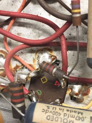
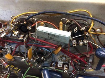
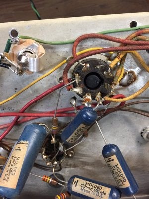
I recently picked up this early 60's Tonemaster Troubadour 214 in a trade. It's got a great story with it; the guy I got it from did a bunch of yard work for an older lady in his neighborhood and he received it as payment. Her late husband was a guitar player, but after he got older and passed away it apparently sat in a barn. Everything was 100% original when I got it, including the vintage Telefunken preamp tubes and Sylvania 6V6s! Everything worked fine (before I got hold of it, ha!) except for some occasional crackling.

IZeDJVR.jpg


YPFm6ql.jpg


RnD2JnT.jpg


I'm not expert on these, but from what I've researched the circuit on this model is similar to the Magnatone 213. Here's a gut shot:

F3YOsmx.jpg


I bought a few parts last week including a 3-prong cord, a speaker jack to add to the chassis since the speaker was originally hardwired to the output transformer, and one of the replacement twist lock electrolytic cans that CE Manufacturing makes. Even though the original can wasn't bulging or showing signs of leaking, I figured it was a good idea.

I did the 3-prong power cord/death cap removal and speaker jack individually first and everything worked fine after those mods. Yesterday afternoon I finished up replacing the electrolytic can but now I'm getting no output at all; the volume/tone controls have no effect. If I turn up the vibrato controls though, you can hear the vibrato depth/speed oscillation coming from the speaker. I took a LOT of pictures beforehand of the wiring on the cap and drew a diagram; I've gone over them several times to recheck connections, verify continuity, chopsticked the wires but can't find anything wrong. Any ideas on the lack of sound?

Old cap:
x4AGkih.jpg


New one:
LhyLHT1.jpg


All of the terminals on the cap are getting DC voltage; half circle = 388v, square = 364v, triangle = 356v, and 20v on the fourth terminal (this one ties to Pin 8 on a power tube, which also ties to pin 1 on the rectifier).

I haven't been able to find the exact schematic for the 214, but here's one for a 213 which *I think* should be pretty close:
http://www.magnatoneamps.com/schematics/magnatone_213.pdf
 

Wally

Telefied
Ad Free Member
Joined
Mar 17, 2003
Posts
46,337
Location
Lubbock, TX
That is true point to point....enjoyable mess, isn’t it? Have you made up a voltage chart?
 

peteb

Poster Extraordinaire
Joined
Apr 25, 2003
Posts
7,406
Location
Cascadia
In descending order, the cap can connects to:

1. rectifier and OT center tap > plates of power tubes

2. Screens of power tubes

3. Trem

4. Preamp plates


Pin 8 of the power tubes are the cathodes and should not be connoted to any B+, but would be around 20 VDC.


The 4th filter cap terminal should be a couple hundred volts DC to power the preamp. If this is connected to pin 8 on the power tubes, that is a problem.
 

GoKart Mozart

Tele-Meister
Joined
Aug 30, 2012
Posts
167
Location
Killen, AL
That is true point to point....enjoyable mess, isn’t it? Have you made up a voltage chart?

Oh man...”rat’s nest” isn’t too far off the mark when describing it! Haha

I did make a voltage chart and I’ll post it after I get home this evening.
 

GoKart Mozart

Tele-Meister
Joined
Aug 30, 2012
Posts
167
Location
Killen, AL
In descending order, the cap can connects to:

1. rectifier and OT center tap > plates of power tubes

2. Screens of power tubes

3. Trem

4. Preamp plates


Pin 8 of the power tubes are the cathodes and should not be connoted to any B+, but would be around 20 VDC.


The 4th filter cap terminal should be a couple hundred volts DC to power the preamp. If this is connected to pin 8 on the power tubes, that is a problem.

Pete, thanks for looking! Wow, that’s interesting regarding the power cathode on the 4th cap terminal. Here are a couple of pics I took before I removed the factory can and what I wrote down before I removed it. The yellow wire was definitely running to the cathode/Pin 8 on the power tube.

1) Red wire to rectifier Pin 2
2) orange wire to power tube screen
3) red wire to power tube pin 6, which is just jumpering over to the vibrato circuit. Also has Red wire to rectifier Pin 5.
4) Yellow wire to power tube cathode - Pin 8. You can see in the pic below that this is how it was originally hooked up:

968E6291-47B8-4765-B8D7-38578654EF5E.jpeg

F10E4BA3-35E4-4FB7-849B-0C57CED52C84.jpeg
 

GoKart Mozart

Tele-Meister
Joined
Aug 30, 2012
Posts
167
Location
Killen, AL
After looking again, I don’t believe the schematic I originally posted is accurate for my amp. Since the components on mine date to the early 60’s, I think these two later versions would be more accurate.

1)Model 213A:
http://www.magnatoneamps.com/schematics/magnatone_213-a.jpg

2) This was a later evolution (model 413) that replaced the 12AX7 oscillator with a 6AV6 and some tone switches in the preamp:
http://www.magnatoneamps.com/schematics/magnatone_413.png

Both show the extra cap terminal going to the power cathodes...but it looks like there should be a 250 ohm resistor going to ground as well??
 

D'tar

Friend of Leo's
Joined
Jan 11, 2013
Posts
4,174
Location
WNY
IIRC... One of the terminals is a ground. The 250r resistor is possobly after the can terminal which 20v there would be reasonable. Could they be using the 20mfd can as a cathode bypass? It shouldnt take tooooo long to draw out what is happening there. Good luck, that will be a great amp when healthy!
 

peteb

Poster Extraordinaire
Joined
Apr 25, 2003
Posts
7,406
Location
Cascadia
Good call D’tar.


Notice how the 4th cap on the original cap can is only rated for 25 volts, just right for a cathode bypass cap.
 

dan40

Friend of Leo's
Joined
Aug 19, 2015
Posts
3,868
Location
Richmond Va
Can you locate a power resistor between pin 8 of the power tubes and a ground location? Like D'tar mentioned, you need a bias resistor for the power tubes to function.
 

peteb

Poster Extraordinaire
Joined
Apr 25, 2003
Posts
7,406
Location
Cascadia
There must be a cathode resistor or else there would be no voltsge on the cathode.

It looks to be the white ceramic resistor.


Why does the cathode connect to pin 1 of the rectifier tube?


Pin 1 is unused?
 

GoKart Mozart

Tele-Meister
Joined
Aug 30, 2012
Posts
167
Location
Killen, AL
IIRC... One of the terminals is a ground. The 250r resistor is possobly after the can terminal which 20v there would be reasonable. Could they be using the 20mfd can as a cathode bypass? It shouldnt take tooooo long to draw out what is happening there. Good luck, that will be a great amp when healthy!

Can you locate a power resistor between pin 8 of the power tubes and a ground location? Like D'tar mentioned, you need a bias resistor for the power tubes to function.

There must be a cathode resistor or else there would be no voltsge on the cathode.

It looks to be the white ceramic resistor.


Why does the cathode connect to pin 1 of the rectifier tube?


Pin 1 is unused?

Yes, I believe it’s the blocky looking 250ohm resistor. It goes from the cathode /pin 8 on the right-hand power tube over to ground.
26D71F29-EF90-46DA-BE52-F8CBA831A799.jpeg

Here’s a better view showing the mystery terminal tied to the cathode. As you can see, I haven’t touched the original solder joint on that cathode!
8D4F3733-5EEF-4B52-A00A-FFE6E2AA84F7.jpeg

Pete, here’s a close up of the rectifier. The plastic yellow wire runs to pin 1 along with a green/yellow wire coming out of the power tranny.

50756A66-2131-490D-9823-815206DF34E2.jpeg

I REALLY appreciate you guys taking a look at this!
 

GoKart Mozart

Tele-Meister
Joined
Aug 30, 2012
Posts
167
Location
Killen, AL
Here’s the voltages:

V1 - 12AX7
—————-
1: 143
3: 1
6: 138
8: 1

V2 - 12AX7
------------
1: 152 (POP)
3: 2
6: 233 (POP)
8: 121 (POP)

V3 - 12AU7. This one is connected to the varistors in the vibrato circuit and lots of the pins show voltage:
------------
1: 334
2: 182
3: 191
6: 244
7: 45
8: 90

V4 - 12AX7. I didn't record voltages here because I think this one is the oscillator circuit...the voltages were jumping all around the place with the vibrato speed turned up.

V5 - 6V6
---------
3: 379
4: 369
8: 20

V6 - 6V6
----------
3: 389
4: 369
8: 20

Can cap is showing 394, 271, 362, and 20.
 

peteb

Poster Extraordinaire
Joined
Apr 25, 2003
Posts
7,406
Location
Cascadia
I REALLY appreciate you guys taking a look at this!

You are welcome.

It’s interesting looking into different amps.


The voltages mostly look good, I can’t comment on the trem voltages however.


The one that seems odd is pin 8 on v2, the cathode.


Pin 8 is the cathode and would normally be low, like pin 3, except if it’s cathode follower or whatever, but that would be odd for such a simple amp with what looks like only two pre amp gain stages.


I still think pin 1 on the recto is unused for rectifying and is being used for something else.


I think I know. The green/yellow wire from the PT should be the center tap for the filament circuit and normally would be grounded. The cathodes of the power tubes connect to ground, but being cathode biased, the cathodes are elevated at 20 volts by the cathode resistor. In this case they chose to elevate the filament center tap as well, for hum reduction.
 

D'tar

Friend of Leo's
Joined
Jan 11, 2013
Posts
4,174
Location
WNY
Are those ALL the (POP)s you heard? Are the volumes up? What about V2 p2?

V2b should be the phase inverter. Voltage on p7 should be noted as well.
 

GoKart Mozart

Tele-Meister
Joined
Aug 30, 2012
Posts
167
Location
Killen, AL
The voltages mostly look good, I can’t comment on the trem voltages however.

The one that seems odd is pin 8 on v2, the cathode.

Pin 8 is the cathode and would normally be low, like pin 3, except if it’s cathode follower or whatever, but that would be odd for such a simple amp with what looks like only two pre amp gain stages.

I thought it was strange as well, especially compared to what you’d see like on a 5E3...however, take a look at this model 413 schematic that I posted above. Toward the top of the page, it shows the cathode voltage for V2 to be 100v (if i’m following the schematic correctly):
http://www.magnatoneamps.com/schematics/magnatone_413.png
 

GoKart Mozart

Tele-Meister
Joined
Aug 30, 2012
Posts
167
Location
Killen, AL
Are those ALL the (POP)s you heard? Are the volumes up? What about V2 p2?

V2b should be the phase inverter. Voltage on p7 should be noted as well.

Volumes were up. There was some popping on V3 (vibrato circuit), none on V1 or V4, and none on either power tube.

V2 p2 does not pop. V2 p7 shows 5v.
 

D'tar

Friend of Leo's
Joined
Jan 11, 2013
Posts
4,174
Location
WNY
So you are losing the signal at the grid of V2, no pop. The output tubes may be more of a scrathing sound but the fact that you get pops from the preamp tubes tells us they are conducting through to the speaker. Im not going to pretend that I fully understand whats happening with V3 and V4. I might recommend swapping a new tube in V2, maybe switch with V4 or a known good 12a_7. Maybe fill in the rest of your voltage chart just in case something else is going on. Dc on all pins and ac on the heaters.

Edit... V2b vdc looks good to me
 

peteb

Poster Extraordinaire
Joined
Apr 25, 2003
Posts
7,406
Location
Cascadia
Good find. That is the cathodyne phase inverter and the cathode should be at the higher voltage.


That schematic does look accurate for the amp. The filament center tap is connected to the cathodes of the power tubes.


It all makes sense except it’s not working.


If you are sure you connected the new cap can as the old one was, I believe you.


For an amp where the DC checks out but there is no sound, all I can think to do is start checking the AC signal.
I just use a guitar and a DMM. Start at the power tubes, grid or plate, is there signal?
 
Top