Tele tone knob has no effect on neck pickup

drhender

TDPRI Member
Joined
Jul 28, 2025
Posts
5
Age
52
Location
North Carolina, US
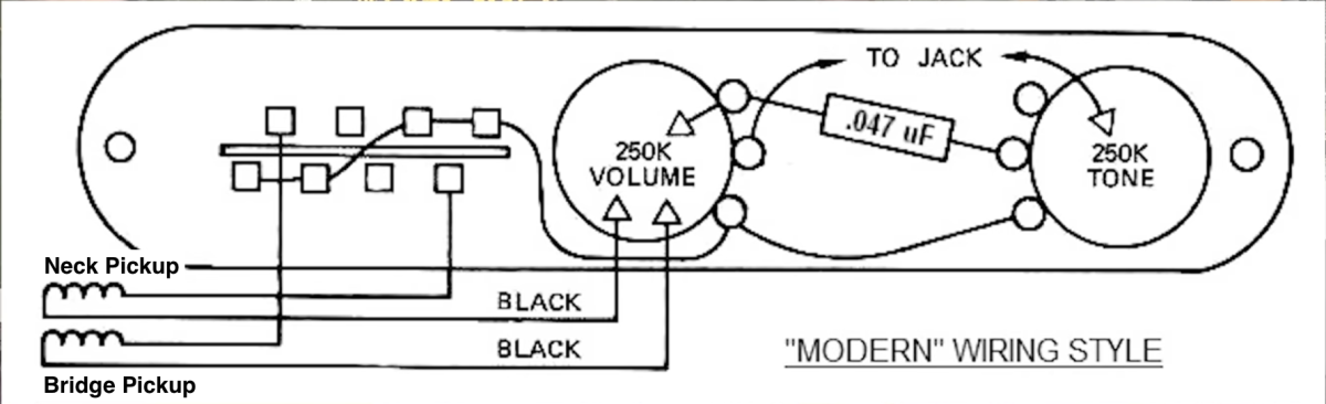
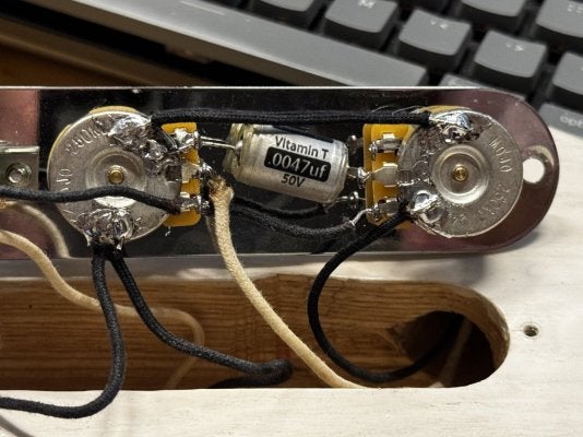
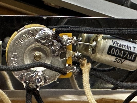
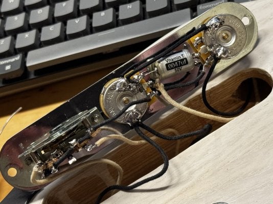
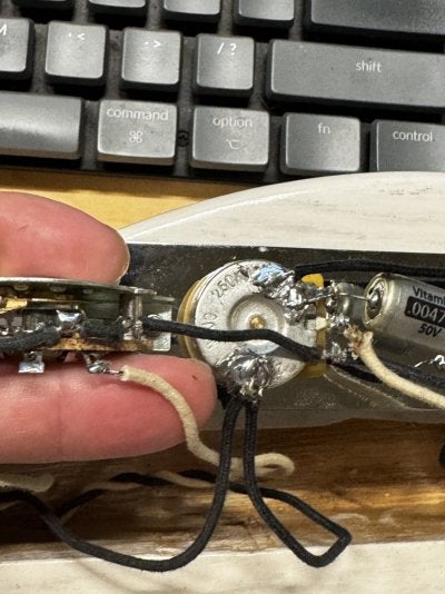
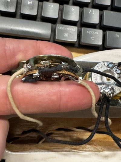
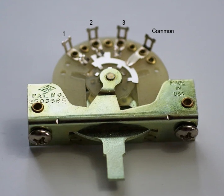
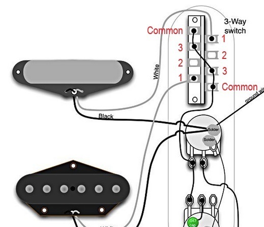
I wired up a tele that I built with a friend using 250K pots and a 0.047uf cap. However, the tone pot seems to have no effect on the neck pickup. I am using the the standard "modern" 3-way tele wiring (diagram attached.) Last night, I went through and replaced each pot and the cap one-by-one, but that didn't fix (or even change) the problem. I am using a pair of Virgil Arlo single coil pickups.

Does anyone have any suggestions as to what might be the problem? Any advise or suggestions are greatly appreciated!
 

Attachments

  • Tele modern wiring.png
    Tele modern wiring.png
    175.9 KB · Views: 58

Peegoo

Telefied
Ad Free Member
Joined
Oct 11, 2019
Posts
31,577
Location
Beast of Bourbon
@drhender

If you have signal from both pickups routing correctly through the three switch positions, along with the volume control affecting both pickups, there's no way the tone control can function only on the bridge pickup unless the circuit is miswired.

Have a second pair of eyeballs check your work; it's easy to miss obvious stuff after looking at it 50 times.

It happens to the best of us; last week I miswired a Strat and it drove me NUTS, so I took two days off and then came back to it. And I spotted my mistake right away.

Welcome to the crazy house!
 

drhender

TDPRI Member
Joined
Jul 28, 2025
Posts
5
Age
52
Location
North Carolina, US
Hmmm... I've looked over things again, but nothing is popping out to me. I'm attaching photos of the work with close-ups of each component. Be gentle on my soldering. I am used to working on much smaller surface mount components-- not these great big pots that soak away the heat as fast as I can apply it.

Again. I really appreciate you all taking the time to attempt to help the new guy.
 

Attachments

  • IMG_4145.jpeg
    IMG_4145.jpeg
    195.4 KB · Views: 63
  • IMG_4144.jpeg
    IMG_4144.jpeg
    179.2 KB · Views: 61
  • IMG_4143.jpeg
    IMG_4143.jpeg
    180.5 KB · Views: 52
  • IMG_4142.jpeg
    IMG_4142.jpeg
    195.6 KB · Views: 54
  • IMG_4147.jpeg
    IMG_4147.jpeg
    207.8 KB · Views: 63

frisco slim

Tele-Holic
Joined
Jan 4, 2019
Posts
661
Location
USA
In your wiring diagram in post #1, the neck and bridge pickups are swapped. In position 3, when you think you're getting neck pickup, you're actually getting bridge pickup. @ChicknPickn's diagram in post #2 is correct.
 

Peegoo

Telefied
Ad Free Member
Joined
Oct 11, 2019
Posts
31,577
Location
Beast of Bourbon
@drhender

Everything appears to be wired properly. I'm wondering if it's the switch. Not all switches are made the same way. Some are flipped 180 degrees in the way tne conductive wafers on both sides (poles) of the switch are laid out. Here's what I mean.

Each side of the switch has four tabs: 1, 2, 3, and Common. Note how the Common tab is always in contact with the sliding wafer's conductor, no matter which position the switch is set on. Some switches are backward from most diagrams you find online.

qbvy1iO1_o.jpg


Tabs 3 and Common are the ones on both sides that connect to the volume pot. Look at the tabs on your switch and make certin it's wired like this:

fH8Rn0JY_o.jpg
 

GTO

Tele-Holic
Joined
Apr 3, 2005
Posts
824
Location
Peak District
It's probably staring you in the face but a case of not seeing the wood for the trees (I have many times), but I'd simply follow the diagram in post #2, sometimes a fresh take in it works wonders.
 

Boreas

Telefied
Ad Free Member
Joined
Nov 3, 2019
Posts
20,703
Age
70
Location
Adirondack Coast, NY
The capacitor appears to be .0047uF not .047uF.
Bingo!! Swapping it for the correct value should do the trick! Personally, I would just do a ~0.047 or slightly lower wafer soldered to the T pot. Otherwise, I would use an Orange Drop soldered like you have it.

You soldering looks acceptable - nice and shiny which usually means no cold joints. Is it lead or lead-free (often shinier)? Lead requires less heat if you are having trouble. Most dining-room table modders use lead. I prefer Kester and a CLEAN, TINNED, chisel tip.

Welcome aboard!
 
Last edited:

frisco slim

Tele-Holic
Joined
Jan 4, 2019
Posts
661
Location
USA
I am using the the standard "modern" 3-way tele wiring (diagram attached.)

Let me repeat what I said in post #8. The "standard 'modern' 3-way tele wiring" diagram you posted in post #1 is NOT CORRECT. It has the bridge pickup positive lead going to where the neck pickup positive lead should go, and vice versa. Did you wire your harness per that diagram? If you put the switch in position 3 (switch knob towards headstock) and tap on the pickups, do you hear a sound from the neck pickup? From the bridge pickup?

@ChicknPickn's diagram in post #2 shows the correct wiring.

The .0047uF vs .047uF cap is also a valid concern, but a separate matter. Once the wiring is correct, you should still hear some effect of the tone control even with the smaller cap. From about 10 to 5 on the tone pot the cap value makes very little difference.
 
Last edited:

Geo

Poster Extraordinaire
Joined
Mar 17, 2003
Posts
5,937
Age
76
Location
Hendersonville, TN
I can't see close enough to, but the black wire from the volume lug going to the switch tab connections are worth checking for making contact especially the one for the neck.
 

GTO

Tele-Holic
Joined
Apr 3, 2005
Posts
824
Location
Peak District
Let me repeat what I said in post #8. The "standard 'modern' 3-way tele wiring" diagram you posted in post #1 is NOT CORRECT. It has the bridge pickup positive lead going to where the neck pickup positive lead should go, and vice versa. Did you wire your harness per that diagram? If you put the switch in position 3 (switch knob towards headstock) and tap on the pickups, do you hear a sound from the neck pickup? From the bridge pickup?

@ChicknPickn's diagram in post #2 shows the correct wiring.

The .0047uF vs .047uF cap is also a valid concern, but a separate matter. Once the wiring is correct, you should still hear some effect of the tone control even with the smaller cap.

That's it isn't it, I guess it's natural we take a wiring diagram to be correct so you look for something more complicated, but this really was staring us in the face.
 

Piggy Stu

Poster Extraordinaire
Joined
Feb 26, 2017
Posts
5,444
Location
UK
Not that my eyesight or wiring knowledge can contribute here, but I bought a fretless bass a couple of months ago that the previous owner 'modded'

Yes, I know this word means 'ruined and decided to dump his broken bass', but that's why I got it cheap

I knew when I bought it that the knobs made pretty much zero difference. I was going to unscrew the control panel and try to work it out, but this post has reminded me that people on here not just know 1000 times more than I ever will, but enjoy the diversion of looking at it and finding the missing jigsaw piece, so watch out for incoming post to spot some wonky wiring
 

Tuxedo Poly

Friend of Leo's
Joined
Dec 19, 2011
Posts
2,727
Location
Merseyside UK
This is a modified Seymour Duncan wiring diagram which copies the factory wiring found on many Fender Telecasters. It may help.
SD_standard_tele_mod.jpg
 

philosofriend

Tele-Afflicted
Joined
Oct 28, 2015
Posts
1,707
Location
Kalamazoo
This is not a Stratocaster that has the tone control circuit intimately routed through the pickup selector switch.

In this tele circuit, if the tone control works on one pickup it has to work on the other pickup. The tone is hooked directly to the volume pot so that if the volume pot is working on a pickup, the tone control has to be there trying to change the sound if the cap has a large enough value. The problem has too be that the cap is too small too audibly affect the particular pickup in its particular position on the guitar. Find a cap value that sounds acceptable with each pickup.

I have a guitar where I overthought the circuit: the five way pickup super switch is hooking in a different tone cap for each position. Yikes! You are not fighting this type of problem.
 
Last edited:
Top