slider switches wiring help needed

  • Thread starter 2after909
  • Start date
  • This site may earn a commission from merchant affiliate links like Ebay, Amazon, and others.

2after909

Tele-Holic
Joined
Dec 23, 2010
Posts
617
Location
brooklyn, ny
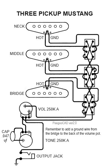
I've got a guitar with 3 pickups and I want to use on-on slider switches (they look like the ones on fender jaguars and mustangs) to turn the 3 pickups on and off individually. I want the signal from all 3 pickups to go to the volume and tone pots. Somehow I can't figure out how to do it. Can anyone advise? Or maybe point me to a schematic that will work? Thanks.
 

Peegoo

Telefied
Ad Free Member
Joined
Oct 11, 2019
Posts
31,576
Location
Beast of Bourbon
@2after909

The Mustang circuit will work. All you need to do is add another switch for the 3rd pickup in series. This configuration will give you on/off and in/out-of-phase for each pickup.

Rpzh4psK_o.jpg
 

2after909

Tele-Holic
Joined
Dec 23, 2010
Posts
617
Location
brooklyn, ny
@2after909

The Mustang circuit will work. All you need to do is add another switch for the 3rd pickup in series. This configuration will give you on/off and in/out-of-phase for each pickup.

Rpzh4psK_o.jpg
@2after909

The Mustang circuit will work. All you need to do is add another switch for the 3rd pickup in series. This configuration will give you on/off and in/out-of-phase for each pickup.

Rpzh4psK_o.jpg
Thanks.

Huh. My on-on switches only have 6 lugs on them. I wonder how to adapt this…
 

Peegoo

Telefied
Ad Free Member
Joined
Oct 11, 2019
Posts
31,576
Location
Beast of Bourbon
Thanks.

Huh. My on-on switches only have 6 lugs on them. I wonder how to adapt this…

You have a DMM, right? You can use it to test a switch and determine which pairs of solder tabs have continuity at all switch positions.

Draw a diagram and take notes. This is a great learning opportunity!
 

2after909

Tele-Holic
Joined
Dec 23, 2010
Posts
617
Location
brooklyn, ny
Uh, I currently have 2 non-fiunctioning DMMs. I understand I could use one to trace how the signal flows through a switch. I was really just hoping for a drawing to show me which lugs to solder which wires to.
 

kbold

Friend of Leo's
Joined
Jul 21, 2015
Posts
3,799
Location
Australia
Uh, I currently have 2 non-fiunctioning DMMs. I understand I could use one to trace how the signal flows through a switch. I was really just hoping for a drawing to show me which lugs to solder which wires to.
Curious. How do you get non-functioning DMM's to trace the signal path?
Even if you use both of them, you will be unsuccessful.

What the above replies are suggesting, is that you need to determine the function/type of switch you are using.
Even buying new ones, this is a good idea, as the manufacturer may package or label switch incorrectly.
 

AAT65

Doctor of Teleocity
Joined
May 29, 2016
Posts
10,008
Location
Edinburgh, Scotland
Thanks.

Huh. My on-on switches only have 6 lugs on them. I wonder how to adapt this…
I think you can just treat your centre lugs as being the same as the pairs of centre lugs in peegoo’s diagram (connect the pickup wires to the centre lugs, connect the cross-crossing output wires to the outer lugs) - and I think it will work whether your 6-lug switches are On/Off/On or On/On/On switches.
But please get yourself a working DMM!
 

Deaf Eddie

Friend of Leo's
Silver Supporter
Joined
Mar 17, 2003
Posts
3,636
Location
Beautiful Idyllwild, CA
If your switches only have SIX lugs (not eight, as in the drawing above), they can easy be wired for on/off, but no Phase option. Here's a quick edit of Peegoo's drawing to show how...

1721085406276.png


Note that he shows the bottom pickup turned around... not necessary for your scheme.
The one thing I don't like about this is that there is an "ALL OFF" position. I'm not sure how that could be overcome in this scheme with the switches you have.

AND get a multimeter!
 

2after909

Tele-Holic
Joined
Dec 23, 2010
Posts
617
Location
brooklyn, ny
If your switches only have SIX lugs (not eight, as in the drawing above), they can easy be wired for on/off, but no Phase option. Here's a quick edit of Peegoo's drawing to show how...

View attachment 1257138

Note that he shows the bottom pickup turned around... not necessary for your scheme.
The one thing I don't like about this is that there is an "ALL OFF" position. I'm not sure how that could be overcome in this scheme with the switches you have.

AND get a multimeter!

Awesome, thanks. I have your 5 position tele wiring, the one with the cocked wah position, in one of my teles and love it. Yes, I’ll get another multimeter.
 

Gsweng

Tele-Holic
Joined
Feb 1, 2021
Posts
553
Age
69
Location
Fort Wayne, IN
You have a DMM, right? You can use it to test a switch and determine which pairs of solder tabs have continuity at all switch positions.

Draw a diagram and take notes. This is a great learning opportunity!
Yes, I always do this with switches so I know exactly what is connected to what before I start soldering. Otherwise, you are just guessing. Measure the magnetic polarity, check which pickup leads are start/finish, the switching configuration for each position, etc. Get it straight in your head so you know it will/won’t work. Some schematics gotten on-line can be wrong. I’ve found that Seymour Duncan schematics are always right (but I check anyway).
 
Top