SF Vibrosonic Reverb mod(s)

  • Thread starter shinbones_jr
  • Start date
  • This site may earn a commission from merchant affiliate links like Ebay, Amazon, and others.

shinbones_jr

TDPRI Member
Joined
Jan 17, 2025
Posts
29
Age
52
Location
Perth, West Oz
I recently acquired a non-working 1974 Vibrosonic Reverb and brought it back to life with new electrolytic caps throughout and new (freshly reconed) EVM-15L speaker. It now works fine... with all voltages correct(ish) per the schematic and everything else doing what it should. I love it, but find it sounds very ice-picky, especially at higher volumes.

I've made a few of the mods described by @robrob at his awesome website. These include adding adjustable bias, slowing the tremolo and reducing tremolo tick. I'll attach a schematic including my all mods below.

Mine is the push-pull master vol variant and before I saw @CoolBlueGlow's recent thread on taming the crappy pull-for-distortion function, I decided to delete that entire circuit and utilise the pull-switch for optional reduced NFB. So now the amp has the stock NFB circuit (820ohm w/100ohm shunt) when the switch is pulled, and light NFB (2.2k+820ohm w/100 ohm shunt) when the switch is pushed in.

To tame the ice-pick, I've put a 0.01uF cap across the stock 820ohm NFB resistor. I like what that does to the tone with the stock NFB setting but when I push the MV in for reduced NFB there's still too much ice-pick.

So I figure I need to add a cap across the 2.2k NFB resistor to let the ice-pick highs pass, but I can't work out what value cap I should put in parallel with the switchable 2.2k resistor to get the same frequencies bypassing the resistor as I'm getting from the the 0.01uF/820ohm combo. At this point my ambitions exceed my theoretical knowledge so I'm asking for help. Can anyone please tell me what value cap I should add where I've put the '?' on my attached schematic?

FWIW, the other half of the DPST MV switch is now spare and could be used if that helps.

With thanks,
Scott
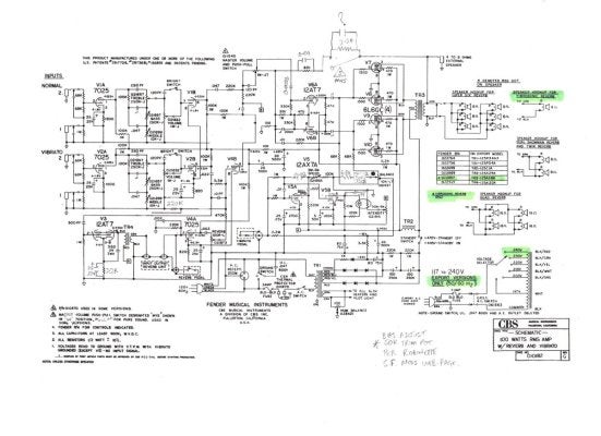
Shinbones_Vibrosonic Reverb_Schematic.jpg
 

GotA24Fretter

Tele-Holic
Joined
Jan 3, 2024
Posts
879
Age
38
Location
TX
Look up "RC filter calculator". You'll be able to plug in values for resistance and capacitance to get to the same frequency as your reference. This will get you there but won't teach you much.

Alternatively you can look up the equation for a first order RC filter and read up. Once you get your head around what you've learned, you'll see the equations for one set of components (R1 and C1) are equal to the other (R2 and C2) when you're wanting them to have the same frequency. Think back to your algebra classes to recall they can be rearranged such that if you multiply R1 and C1 that it should equal the product of R2 and C2. In other words R1xC1/R2 will give you the C2 you're looking for. Choose the nearest standard cap value.

Finally, if you try this and don't like the effect, then I would suggest attempting to tame the high end a different way that doesn't rely on the NFB. Some options are plate bypass caps on preamp stage triodes, a small value cap across the plates of the PI (maybe 470-680pf to start?), or the Vox type cut control that is illustrated on Rob's site. If you use a no-load pot for the cut control then it is totally out of circuit at max rotation.
 
Last edited:

shinbones_jr

TDPRI Member
Joined
Jan 17, 2025
Posts
29
Age
52
Location
Perth, West Oz
Look up "RC filter calculator". You'll be able to plug in values for resistance and capacitance to get to the same frequency as your reference. This will get you there but won't teach you much.

Alternatively you can look up the equation for a first order RC filter and read up. Once you get your head around what you've learned, you'll see the equations for one set of components (R1 and C1) are equal to the other (R2 and C2) when you're wanting them to have the same frequency. Think back to your algebra classes to recall they can be rearranged such that if you multiply R1 and C1 that it should equal the product of R2 and C2. In other words R1xC1/R2 will give you the C2 you're looking for. Choose the nearest standard cap value.

Finally, if you try this and don't like the effect, then I would suggest attempting to tame the high end a different way that doesn't rely on the NFB. Some options are plate bypass caps on preamp stage triodes, a small value cap across the plates of the PI (maybe 470-680pf to start?), or the Vox type cut control that is illustrated on Rob's site. If you use a no-load pot for the cut control then it is totally out of circuit at max rotation.
Thanks for your reply @GotA24Fretter.

I understand, based on RC filter calculators, the .01 cap & 820 ohm resistor give a cutoff frequency of 19.41kHz, and
the cap required for the same cutoff frequency with a 2.2K resistor is 0.0037uF.

What I’m struggling with is:
1) I don’t understand how two RC filters in series will interact with each other.

I understand the two resistors in series will sum to 3.02k and the two caps to 0.0027uF. But I don’t know if that means I need to increase either or both of the caps, or by how much, to get my desired outcome.

2) The ratio of the NFB series to shunt resistor/s will change when the extra filter stage is engaged, meaning much less of the NFB signal gets to the PI. I’m not sure how (or if) I can compensate for that.

I think I need to look into your alternative suggestions for taming the high end.

Thanks again 👍
 

shinbones_jr

TDPRI Member
Joined
Jan 17, 2025
Posts
29
Age
52
Location
Perth, West Oz
What are your settings on the amp when playing?
Still learning to dial it in, but with a strat on the neck pickup: Treble 3-4, mid 5-6, bass 4-5 is working for me.
FWIW, I can get a decent tone without too much icepick with the master vol around 6. If I wind up the master any more it seems to get really shrill.
 

Wally

Telefied
Ad Free Member
Joined
Mar 17, 2003
Posts
46,337
Location
Lubbock, TX
Interesting. With those settings, I have never heard any Bf/SF reverb amp to be problematic with regard to trebles…even in the bridge p-up. I always set an amp up on the bridge P-up.
If you fret the last fret, how close to the strings are the pickup poles?
 

shinbones_jr

TDPRI Member
Joined
Jan 17, 2025
Posts
29
Age
52
Location
Perth, West Oz
Interesting. With those settings, I have never heard any Bf/SF reverb amp to be problematic with regard to trebles…even in the bridge p-up. I always set an amp up on the bridge P-up.
If you fret the last fret, how close to the strings are the pickup poles?
Will check string height vs pickups and let you know tomorrow @Wally but I don’t think that’s the problem.
I don’t have the same issue with my SF Champ or my two BF reverb-ish Allen Amps (Sweet Spot & Chihuahua- both running 6L6GC’s).
 

Wally

Telefied
Ad Free Member
Joined
Mar 17, 2003
Posts
46,337
Location
Lubbock, TX
If I am looking for big and clean, I run that MV at 10. The signal gains some big low end that way, ime. If I am looking for a ‘hot’ amp in. BF:SF amp, I start modding the Normal channel….separate the pin 8 cathodes, different voicing and gain, add the effects there.
Before I do that, I would find out why this particular amp is doing what it is doing. Odd it is, imho/ime. Have you run the amp through some different speakers…..maybe one of those Allen’s’ speakers?
Good luck with it.
 

uriah1

Telefied
Ad Free Member
Joined
Feb 12, 2011
Posts
33,493
Location
Around
I had a vrrb that I had a tech do some of the mods to.
Had to have some reversed later. imho
 

shinbones_jr

TDPRI Member
Joined
Jan 17, 2025
Posts
29
Age
52
Location
Perth, West Oz
Thanks everyone for your suggestions.

I spent some time this afternoon trying different caps across the phase inverter plates to tame the ice-pick. I found 500pF helped. I then tried A-B-ing my Vibrosonic with my Allen Amps Sweet Spot. The Sweet Spot is much warmer than the Vibrosonic but that’s not surprising… they’re two very different beasts.
But it gave be a tone/treble benchmark to aim for, so I played around with the Vibrosonic’s treble pot and managed to dial the ice-pick highs mostly out. I found the treble pot has a notch or spike in its response right about 3 that I hadn’t noticed before. Below the notch it gets too muffled almost immediately. Just above the notch… say 3 & 1/4 it gets too bright very quickly. Around 3 on the treble pot is the Goldilocks setting for this amp & speaker, with my ears and my #1 strat at least. Not used to having such a low treble setting on a Fender BF/SF (or similar) amp, but that’s where it sounds right.
I’m gonna pack the soldering iron away for now and just play it!
Thanks again everyone.
 
Last edited:

Pete Farrington

Tele-Afflicted
Joined
Feb 18, 2023
Posts
1,716
Location
Staffordshire UK
Have you run the amp through some different speakers
Exactly.
Assuming the amp is working correctly, the fact such a classic circuit is so fussy in finding a pleasing tonal balance is a strong indication that the speaker isn't a good match for it, in this particular usage scenario.

The 'all J' pot tapers used in later silver panels may be a contributing factor.
 

shinbones_jr

TDPRI Member
Joined
Jan 17, 2025
Posts
29
Age
52
Location
Perth, West Oz
Exactly.
Assuming the amp is working correctly, the fact such a classic circuit is so fussy in finding a pleasing tonal balance is a strong indication that the speaker isn't a good match for it, in this particular usage scenario.

The 'all J' pot tapers used in later silver panels may be a contributing factor.
You’re probably right @Pete Farrington (and you too @Wally) but I don’t currently have another cab or speaker that will handle 100W to substitute.
Closest I have is a 12” Eminence Maverick (75W) in my Sweet Spot combo which I should probably give a go, gently.
The original speaker, a Fender-branded PS-15 made by Cerwin Vega was DOA when I acquired the amp and has been sent away for a re-cone. I expect it to also be very bright though, especially as it has an aluminium dust-cap.
 

NTC

Friend of Leo's
Joined
Mar 17, 2003
Posts
2,399
A couple things that I noticed in that schematic:

1. The coupling capbinto the PI is 0.0033uf (or 3.3nf or 3300pf), which looks like it was penciled in. The Fender amps could have anything from 500pf to 0.01uf. Higher values would be darker. What was the original value?
2. That 120pF at the master volume looks like it is there to add highs. Have you tried disconnecting it? This effect should go away if the master volume is all the way up.
3. The speaker may have the wrong conebor needs to break in more. How does it sound with the Allen amp?
 

shinbones_jr

TDPRI Member
Joined
Jan 17, 2025
Posts
29
Age
52
Location
Perth, West Oz
A couple things that I noticed in that schematic:

1. The coupling capbinto the PI is 0.0033uf (or 3.3nf or 3300pf), which looks like it was penciled in. The Fender amps could have anything from 500pf to 0.01uf. Higher values would be darker. What was the original value?
2. That 120pF at the master volume looks like it is there to add highs. Have you tried disconnecting it? This effect should go away if the master volume is all the way up.
3. The speaker may have the wrong conebor needs to break in more. How does it sound with the Allen amp?
Thanks for your reply @NTC.
1. Well spotted 👍. The PI coupling cap was originally 0.01uF (10nF). This change was recommended to let less low frequency through, thus preventing bottom end flub at high volume.
Apparently when Fender changed the PI grid leak resistors from 1M (BF) to 330k (decreased by 1/3, SF), they changed to PI coupling cap from 0.001uF to 0.01uF (increased by x10.) Logically a x3 increase would have been more appropriate, which is what I’ve done. I only made the change a couple of days ago, and can’t hear any appreciable difference in the high frequency response since. Bottom end seems a bit tighter though.

2) Haven’t tried disconnecting the MV bright cap, because I’ve been keeping the MV at 10 to keep that cap out of the equation. Tempted to give it a go though.

3) Just tried the Vibrosonic through the Sweet Spot’s speaker. Was hoping this would be the ‘aha’ moment, but ice pick highs are still there if I dial up the treble past about 3.5.

Another observation FWIW: I’m getting the same symptoms on both the normal and vibrato channels.
 
Last edited:

Wally

Telefied
Ad Free Member
Joined
Mar 17, 2003
Posts
46,337
Location
Lubbock, TX
Re: that Cerwin Vega ….you can have something other than an aluminum dust cover installed on that speaker. Impersonally find no reason to accentuate the high end with an aluminum dust cap on a guitar speaker. Ommv….but I am almost 74 and still have good hearing in all frequency ranges.
Have you tried running this amp with both the Emi 15 and the speaker in the Allen amp just to see if you are not liking a beaming tendency from a single speaker? I doubt if this will change things, but it would eliminate one question/possibilty….however slight that possibility.
I judge the sonics of BF/SF Fenders with volume and tones on 5. I know what I expect to hear even from any pickup on any guitar there. That would be with the MV on 10 in an amp with a MV.
You have an interesting problem there ime.
 

shinbones_jr

TDPRI Member
Joined
Jan 17, 2025
Posts
29
Age
52
Location
Perth, West Oz
Starting to worry now, given that my symptoms seem unusual to others.

Could this gap in my OT laminations be the cause of the ice-pick highs?
IMG_0685.jpeg

I scored this amp not working, literally with smoke coming out of the doghouse, for less than the value of the power tubes late last year. Didn’t realise until I got it home that the speaker was open circuit (but still plugged in) which made me worry about the OT and ‘flyback voltage’.
The OT tests ok for DC resistance, but I do get a bit more voltage fluctuation on the plates when checking bias than I’ve seen in other amps. I’m seeing the plate voltage wobble 1-3VDC (with circa 445V on the plates).
Another observation: I know the eyelet boards can get conductive with moisture. I’m seeing about 3V DC (at the most) relative to ground at some points on the board. Is this enough to cause problems?

Thanks again!
 

corliss1

Poster Extraordinaire
Joined
Sep 13, 2008
Posts
7,884
Location
Lansing, MI
A few thoughts here

I don’t currently have another cab or speaker that will handle 100W to substitute.

Just because your car's speedometer goes up to 120MPH doesn't mean you have to drive it that fast. Unless you're blasting the amp on 10 with distortion, you don't need high power handling just to check the amp into something else.

Could this gap in my OT laminations be the cause of the ice-pick highs?

It's certainly not a good thing, but the only way to know for sure (assuming it measures properly right now) would be to sub in a different OT and see if that changes things.

I’m seeing about 3V DC (at the most) relative to ground at some points on the board.

Yes, that would be up there with some of the worst board conductivity I've ever seen. Be sure you're not 0.00000001 inches away from an eyelet and repeat that test. If that measurement is true and confirmed, it may be time to think about more extreme repair measures. There are ways to pull moisture from a board, with varying results, although replacing the board itself is likely quicker and will provide a 100% effective fix.
 

Wally

Telefied
Ad Free Member
Joined
Mar 17, 2003
Posts
46,337
Location
Lubbock, TX
Didn’t realise until I got it home that the speaker was open circuit (but still plugged in) which made me worry about the OT and ‘flyback voltage’.

The problem with having a plug in that speaker Jack with no load on it is not fly back voltage. The problem is that the plug has broken the contact of the shorting Jack with the tip thereby showing the OT an open circuit. That is a problem for an output transformer. The shorting Jack is there to present a short circuit to the OT if one neglects to have a proper load plugged in that Jack. The OTcan deal with a short much better than it can an open circuit.
I have never seen an OT with that type of problem. Odd. I suspect that someone has had this amp assessed and did not want to spend money on it. At least you did not pay much for it and can get it running if you want to spend some time and money. If you pay a tech to do the work, your out of pocket expense would probably exceed what one of these might bring….if and when you find someone who wants to deal with the weight. Nice amp when they are running correctly.
 

shinbones_jr

TDPRI Member
Joined
Jan 17, 2025
Posts
29
Age
52
Location
Perth, West Oz
Yes, that would be up there with some of the worst board conductivity I've ever seen.
Ouch.

Be sure you're not 0.00000001 inches away from an eyelet and repeat that test. If that measurement is true and confirmed, it may be time to think about more extreme repair measures.
Confirmed. Once the amp has warmed up there’s anywhere between 1 & 3V showing up all over the board ☹️

There are ways to pull moisture from a board,
Have read about people using a hairdryer. Any other suggestions before I undertake major surgery? Mine is quite heavily waxed.
 

shinbones_jr

TDPRI Member
Joined
Jan 17, 2025
Posts
29
Age
52
Location
Perth, West Oz
I suspect that someone has had this amp assessed and did not want to spend money on it.
Possible. The seller was a full-blown hoarder, and the amp had at least 10 years worth of dust on it, so any assessment would have been a long time ago. He was adamant the amp was working last time he used it, and I don’t think he was lying.

The speaker had seen a previous wiring repair though:
IMG_0694.jpeg
 
Top