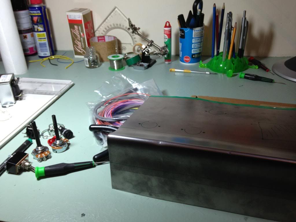
Selmer Little Giant clone build

  • Thread starter MBolanlovechild
  • Start date
  • This site may earn a commission from merchant affiliate links like Ebay, Amazon, and others.

MBolanlovechild

TDPRI Member
Joined
Dec 29, 2011
Posts
93
Location
UK
I have a very basic understanding of valve amp electronics, though I've recently bought the very recommended 'Building Valve Amplifiers' by Morgan Jones and am slowly reading through it, so far it has proved very helpful. My building experience goes as far as a fuzz face clone which I managed to put together once with no problems, although that was a kit..

Unfortunately I am now living amongst other human beings whom share the ability to hear, so I would benefit from a small portable low-wattage amp. Something akin to the little giant would be ideal. I've been lucky enough to try one out in a store and it does produce a lovely sound, however, they're becoming more and more collectible and its getting hard to find any for a fair price; so I thought, it looks like as simple a circuit design as any, why not try building one.

So where to begin, I guess I should start with my plan for the enclosure then move from there to the main layout. I want it to resemble the original in so far as it is compact, but I hear that some people feel the 6 or 8" speaker is a shortcoming. I suppose if I put together the amp before the cab I could run it out to a cabinet and test different speakers before I make a decision.

http://www.vintagehofner.co.uk/gallery/gallery3/gallery4/lgi2.jpg

I've always thought that the layout was a bit precarious, and was done in this way for cost-effective reasons and to accommodate the wider less deep 'radio' style shape.

I prefer the shape and layout of something like the premier 50, which has the chassis on the floor of the amp with tubes mounted upwards.

(link removed)

I imagine that the simplest way of building the circuit would be to use turret board. Just to note, I will try to outline everything I decide to do, no matter how simple it is because i'm likely to make a blinding mistake, so when I say 'i'll mount the tube sockets to the metal chassis', I don't think that would be necessarily controversial, I just don't want to take anything for granted for risk of error. If I do end up putting the chassis on the floor of the amp, then I suppose the output and power transformers can be fixed to the top of the metal chassis. I'd like to have the control panel on the top, or I could mount all of them on a backplate which would make for simpler construction and shorter wire runs. But I think this can be left for later.

Here is the circuit diagram I plan to use

http://www.vintagehofner.co.uk/britamps/selmer/schematic/lgmk3.html

I'll be sourcing most of my parts from ampmaker.com (link removed) , seems to stock most of the things I need, and the prices seem fair.

When it comes to buying caps, how do I decide on the wattage required for each? Also, are there any hard fast rules for which types of resistors are best for certain uses?

I figured that I would start by selecting the transformers first, would these two be suitable?

(link removed)
(link removed)
 

pasquale

Tele-Meister
Joined
Jun 14, 2010
Posts
369
Location
Boston, MA
I think you are on the right path. I highly recommend copying a layout from a similar fender amp, no point in reinventing the wheel and the circuit topography is pretty standard. Have fun.
 

pasquale

Tele-Meister
Joined
Jun 14, 2010
Posts
369
Location
Boston, MA
Oh and on caps worry more about voltage than wattage, 450v should cover you everywhere. That 100k dropping resistor in the B+ rail may require an exercise in Ohm's law to determine the wattage. Go big on that one and the cathode resistor in the power tube. The rest 1/2 watt is ok, 1 watt is better safe than sorry.
 

sjhusting

Tele-Afflicted
Joined
Jul 8, 2003
Posts
1,488
Location
Germany
The output transformer you selected won't work, it is for a push-pull power amp, and you have a single-ended power amp. An output transformer fir a Champ would work - but that is for a 4 ohm speaker so that would limit your speaker choices. The same supplier has another transformer which will work perfectly.

The power transformer is ok although normally you would have a separate 6.3V winding for the EZ80. Total heater current is .3 + .76 + .6 amperes, so 2A will cover you.

The heater winding does not have a center tap so you will have to use an artificial with 2 100 ohm resistors.

I didn't see a fuse on the mains so add that.

Steven
 

MBolanlovechild

TDPRI Member
Joined
Dec 29, 2011
Posts
93
Location
UK
The output transformer you selected won't work, it is for a push-pull power amp, and you have a single-ended power amp. An output transformer fir a Champ would work - but that is for a 4 ohm speaker so that would limit your speaker choices. The same supplier has another transformer which will work perfectly.

The power transformer is ok although normally you would have a separate 6.3V winding for the EZ80. Total heater current is .3 + .76 + .6 amperes, so 2A will cover you.

The heater winding does not have a center tap so you will have to use an artificial with 2 100 ohm resistors.

I didn't see a fuse on the mains so add that.

Steven


Yeah I noticed that there was a fuse missing.

I assume this is the output transformer you are talking about?
(link removed)

I think that the main part of the wiring which I do not understand is how power/output transformers are done. I can see which part is the heater circuit and where the centre tap is on the schematic but I do not know how to relate that to an actual transformer. It has always appeared to me that there are more connection points on the actual transformer than schematics display; I'm sure there's a reason relating to how they work why this is the case.

Another confusion i have when interpreting circuits in general is how important it is to follow the precise shape. For example, the centre tap of the larger part of the transformer which goes to the filter caps and ground. Can those be completely separate wires both coming from the same point, one going to the filter caps, the other to ground? Can something similar be done with the heater supply? Can there be 3 separate pairs of wires each coming from the same appropriate points on the power transformer meeting the 3rd / 4th pins of the tube sockets ? Sorry if this is obvious, I've never seen it explained.
 

orangedrop

Friend of Leo's
Joined
Aug 20, 2010
Posts
2,050
Location
New York
Subscribed...
I hope you post a sound file when you are finished.

This looks sweet!

Look at those comp resistors, they are gigantic:eek:

Love it, so simple and beautiful.
 

sjhusting

Tele-Afflicted
Joined
Jul 8, 2003
Posts
1,488
Location
Germany
Yeah I noticed that there was a fuse missing.

I assume this is the output transformer you are talking about?
(link removed)
Yes, that's it.

I think that the main part of the wiring which I do not understand is how power/output transformers are done. I can see which part is the heater circuit and where the centre tap is on the schematic but I do not know how to relate that to an actual transformer. It has always appeared to me that there are more connection points on the actual transformer than schematics display; I'm sure there's a reason relating to how they work why this is the case.

Another confusion i have when interpreting circuits in general is how important it is to follow the precise shape. For example, the centre tap of the larger part of the transformer which goes to the filter caps and ground. Can those be completely separate wires both coming from the same point, one going to the filter caps, the other to ground? Can something similar be done with the heater supply? Can there be 3 separate pairs of wires each coming from the same appropriate points on the power transformer meeting the 3rd / 4th pins of the tube sockets ? Sorry if this is obvious, I've never seen it explained.

Hmm. Ok.

Transformers 'transform' something (electrical) from one thing into another. In the case of power transformers, they transform wall voltage coming in on the 'primary' side to one or more other things on the 'secondary' side.

The transformer you are looking at has two secondaries, one which is marked as '190-0-190' and one called a 'non-CT 6.3V rated at 2A.'

The high voltage (190V) secondary will have three wires - two red ones, and a third which is different than the two red ones. It is often, but not always, red and yellow. This 'different' lead is the center tap. It is connected to the main ground point (not the PE from the wall!!)

Because it is center-tapped, you have to use a "full wave" rectifier. The EZ80 is a "full wave" rectifier. You connect one of the red wires to pin 1, and the other to pin 7 of the ez80 socket.

The filament leads, which will produce 6.3V, are probably green. There is no center tap on this transformer. One lead goes to one side of the filament string, the other lead goes to the other side. But - you have to create an "artificial center tap" so that the filaments have a reference to ground. You do this by soldering a 100-ohm, 2-watt resistor to each of the green leads, solder the other end of the two together, and connect that to the same ground point as the center tap of the high voltage.

Here's a drawing - (link removed)

The primary side has "dual 120/240V primaries" which could mean two things - there are either three wires or four wires. If there are three wires, then you use the two which the documentation for the transformer says are for 240V. If there are 4 wires, then you have to connect two together (but the right two!) and use the other two for the power cord. This should also be documented in the transformer information.

As a side comment, you need to do some reading and get up to speed on basics before you start working with lethal voltages.

steven
 

MBolanlovechild

TDPRI Member
Joined
Dec 29, 2011
Posts
93
Location
UK
Yes, that's it.


Hmm. Ok.

Transformers 'transform' something (electrical) from one thing into another. In the case of power transformers, they transform wall voltage coming in on the 'primary' side to one or more other things on the 'secondary' side.

The transformer you are looking at has two secondaries, one which is marked as '190-0-190' and one called a 'non-CT 6.3V rated at 2A.'

The high voltage (190V) secondary will have three wires - two red ones, and a third which is different than the two red ones. It is often, but not always, red and yellow. This 'different' lead is the center tap. It is connected to the main ground point (not the PE from the wall!!)

Because it is center-tapped, you have to use a "full wave" rectifier. The EZ80 is a "full wave" rectifier. You connect one of the red wires to pin 1, and the other to pin 7 of the ez80 socket.

The filament leads, which will produce 6.3V, are probably green. There is no center tap on this transformer. One lead goes to one side of the filament string, the other lead goes to the other side. But - you have to create an "artificial center tap" so that the filaments have a reference to ground. You do this by soldering a 100-ohm, 2-watt resistor to each of the green leads, solder the other end of the two together, and connect that to the same ground point as the center tap of the high voltage.

Here's a drawing - (link removed)

The primary side has "dual 120/240V primaries" which could mean two things - there are either three wires or four wires. If there are three wires, then you use the two which the documentation for the transformer says are for 240V. If there are 4 wires, then you have to connect two together (but the right two!) and use the other two for the power cord. This should also be documented in the transformer information.

As a side comment, you need to do some reading and get up to speed on basics before you start working with lethal voltages.

steven


I see, thank you for the helpful drawing. I am aware of what a transformer is supposed to do, its just relating the schematic to an actual one that is the problem, it will be much easier with the transformer in front of me. Of course I will make sure that I know how to wire everything up correctly before attempting anything.

I already happen to have all the tubes necessary in my spares box so no need to pickup any. However, I have only the one EZ80 and I've never had a chance to test it. I have a 15w selmer bassist major with an EZ81 rectifier, could I test it in place of that?

Looking through ampmaker.com I can get everything I need there:

Component List:

Power Transformer
Output Transformer
9-pin tube sockets x 3
1/4" Input Jack
1/4" Output Jack
Fuse Holder
On/Off Switch
1M log pot x2
6.3v indicator

Capacitors:

electrolytic-
22uf 450v
32uf 32uf 450v filter cap can (would there be a problem using 2 individual 33uf 400v caps for this?)

non-polarised-
.022uf x2
.1uf x2
.0047uf

Resistors:

1M 1w x2
270k 1w x2
100k 1w
10k 1w
5.6k 1w
2.2k 1w
130 ohm 3w
100 ohm 3w x2

It won't require a large circuit board, so I'll save some money and use the stripboard they supply as apposed to turret board.
 

MBolanlovechild

TDPRI Member
Joined
Dec 29, 2011
Posts
93
Location
UK
Just put in my order for the parts, which came to around 85 pounds including delivery, not too bad. Tomorrow I will be sorting out the materials for the cabinet and the chassis. Hopefully everything will be set to start building over the weekend.
 

MBolanlovechild

TDPRI Member
Joined
Dec 29, 2011
Posts
93
Location
UK


Parts are all here; the chassis is about as crude as could be, (just a bent piece of 1mm aluminium cut to size with tin snips) I'm currently waiting on a Dremel and step drill bit to cut the tube socket holes and the cutout for the power transformer so unfortunately I won't be able to start wiring until the weekend. I will probably swap around the switch and the fuse, so the fuse is closer to the end of the chassis.

I think I have the general layout down, I have some double sided stripboard which I can cut up for single rows where needed. My idea for the grounding scheme will probably be 2 separate rows under the power valve and the preamp valve with their grounds connected with bus wire, I'll then connect that bus wire to the chassis at the input side of the amp.

It has been my understanding that it is perfectly suitable for low-gain amps to use a single ground bus with one connection to the chassis. However, i'm unsure as to where would be the best point to ground the 2 centre taps (including the artificial one from the heater) and the (-) of the filter caps. Should they be connected to the end of the stripboard under the power valve where the 130r resistor grounds? If I went with that scheme, I would end up with 2 ground connections to the chassis, one for the ground bus, and the other for the safety ground coming from the power cord.


Here is the transformer, I'm fairly sure of how to wire it correctly, but please do correct me if i'm wrong. The 2 primary taps which need to be connected are the 120v on the left pair and the 0v on the right pair. The remaining primary taps will go to the 2 top lugs of the switch. It is my understanding that the polarity of the wires going to the switch do not matter.

For the heater wiring, two 100r resistors are soldered to the 6.3v and the 0v taps with the other ends soldered together and run to ground forming the artificial centre tap. 2 wires go from the taps to pins 4 and 5 of the rectifier socket, then another pair of wires go (from 4/5 of the rectifier socket) to pins 4/5 of the power valve socket then to the preamp valve socket. The 4 and 5 pins of each socket are then soldered to each other to complete the heater wiring. 2 wires from the taps will also be run to the 6.3v indicator.

The 190v secondary taps are connected to pin 1 and 7 of the rectifier socket, and the centre tap is run to ground.

I'm afraid things are going fairly slow, I've only got time to work on it during weekends, but by friday I will have all the necessary tools to complete the chassis (I've always wanted a dremel anyway!). For now I will just run the amp out to an old 1x12 cab with a 16ohm 20w vintage Celestion g12s, which has paired up very well with my Selmer bassist major. If things go smoothly I should be able to get it up and running by the middle of the weekend and hopefully even have a sound test to post.

When I eventually consider the actual cabinet, I'll probably build it with a 10" speaker in mind out of some medium-grade plywood.
 

MBolanlovechild

TDPRI Member
Joined
Dec 29, 2011
Posts
93
Location
UK
Just a small progress report.

I've completed the metal chassis, which took a lot more work than I had anticipated. Its a about as primitive as a chassis could be, I think I could have possibly done the bend a bit better. Its larger than it has to be, I've tried to space out the components to keep things simple and to reduce hum; it would probably take a lot more skill to make it properly compact, but this is my first attempt.


I'm going to find shorter fixing screws for the strip-board, and you may notice that there is a screw missing on the rectifier socket.. my carpet for some reason has a way of absorbing everything small and grey that lands on it, so will replace that also.

I've got the layout completely down I think. I could put the vol and tone pots in the obvious space on the chassis, but it will be mounted on the bottom of the cabinet, and I'd prefer to have a separate control panel at the top of the amp for ease of access.


It happens to be that all of my caps are orange drops and i'm not sure what to think about that. I don't know what their tonal qualities are, but I will probably find out soon enough. I am very looking forward to modding this circuit to my preference but best get a sound out of it first!
 

MBolanlovechild

TDPRI Member
Joined
Dec 29, 2011
Posts
93
Location
UK
Also, I think I may have gone too low on the 100k dropping resistor.. I'm replacing the transformer with one that has a 250v secondary, which will give me a B+ of around 275v. So if i'm using ohm's law correctly.

275/100,000 = 2.75w

The 100k resistor I have currently is only 1w.. so I'll need at least a 3w one.
 

bwacke

Tele-Meister
Gold Supporter
Joined
Oct 28, 2007
Posts
395
Location
Toledo, OH
'Not clear on what you're trying to calculate there, but 275 V /100,000 Ohms = 0.00275 Amps. This means that if you put 275 volts across a 100K resistor it will pull a current of 2.75 milliamps.

Ohm's law for power using voltage and resistance is P = E^2/R (Power in Watts = Voltage squared divided by Resistance in Ohms. So 275^2/100,000 = 0.75625 Watts). So 275 Volts across a 100K resistor dissipates a hair over 3/4 of a Watt.

All this is academic. What are you really interested in knowing? I.e., what is the circuit this 100K resistor is in? ...Sorry, dumb question on my part. I just looked up the Selmer circuit. A 1 Watt resistor in the feed for the plates of the ECC-83 is plenty big.
 

laird

Tele-Holic
Joined
Jul 8, 2009
Posts
741
Location
Palm Harbor, FL
When determining the wattage being dissipated by a resistor, it's the number of volts being dropped across that resistor that matters. Measure the actual voltage drop, it's probably around 30-40v, and redo the calculations again. :)
 

bwacke

Tele-Meister
Gold Supporter
Joined
Oct 28, 2007
Posts
395
Location
Toledo, OH
laird,

If you look at the schematic, the 100K resistor feeds only two 220K plate resistors. Worst case they are paralleled and shorted to ground (tube fully conductive) making a total resistance of 110K (the parallel resistors) + 100K (the decoupling resistor) or 210K and would pull around 0.4 Watt. Worse than worst case the 100K decoupler is shorted to ground and must handle the available full voltage drop, 275 volts. I.e., 3/4 Watt. My advice was that the 1 Watt resistor MBolanlovechild already has is sufficient to handle the circuit under any circumstances. I stand by that statement. :)
 

MBolanlovechild

TDPRI Member
Joined
Dec 29, 2011
Posts
93
Location
UK
Thanks for the help with the resistor wattage.

Another progress report. Very close to being finished with the circuitry; I ordered another transformer with a 250v secondary so I can use the EZ80 rectifier tube but the company has a 2-3 week backlog. So, in the meantime I've ordered some 1N4007 diodes and when they arrive i'll wire them up on the tube socket.

I still need to do the artificial centre-tap, the pot wiring, and I need to reverse the 25uf cap on the power valve. I might also rearrange the components on the preamp stage. They're solid and not touching but they shouldn't really be crossing.

Should be ready to turn on in the next couple days when the diodes arrive.


MBolanlovechild

TDPRI Member
Joined
Dec 29, 2011
Posts
93
Location
UK
Just a couple further questions.

Should the artificial centre tap just be a 100r 3w resistor soldered to each of the heater secondaries then both run to ground? I read somewhere that this should be done on the power valve socket pins 3 to 5 and 3 to 4.

Concerning the pot wiring, I have a separate control plate which will be fixed to the top of the amp. There are 3 ground connections which have to be made. One side of both pots, and the wiper of the tone pot. Can these simply be wired to the back of the pots grounding them to the control plate. Or do I have to run a ground wire to the preamp end of the ground bus.
 

MBolanlovechild

TDPRI Member
Joined
Dec 29, 2011
Posts
93
Location
UK
Seem to have had a bit of a snag.

I finished the wiring and I reckon that has been done correctly.

Powered on and the pilot lamp wouldn't turn on and the tubes did not light up; I could hear the power transformer give off the normal wurr, but no output from the speaker obviously. Turned it off, checked the fuses, all fine. Turned it over and checked the voltage on the filter caps, they had certainly charged up fine. The heater wiring looks ok to me, but then I thought, perhaps having a separate pair of wires coming directly off the heater taps to the pilot light would be an issue, I removed the pilot light from the amp and there has been no change.

I've just measured some voltages from the power transformer (whilst turned on). There is no reading from one side of the heater tap to the other, but there is a 280v reading when touching either side of any bit of the heater wiring and the other to ground.

Could the problem be voltage leakage from the primaries? When the amp is on I can measure continuity from the primary windings to the heater secondary, but when off there is no continuity; is that normal?
 

trancedental

Tele-Meister
Joined
Aug 15, 2010
Posts
472
Location
London
I always wire up the heater filaments & test them first, then fit the valves & see if they are lighting normally. Before connecting up the secondaries.

I know it's obvious but are you measuring for AC for the heaters, it's an easy mistake to make, :rolleyes: been there done that!!!

You shouldn't be getting any DC on the heaters Not 280V either! :confused:

Only issue I can see with the PT / rectifier is that the (green) secondary ground wire should be going to a nearby transformer bolt, it looks like it's heading for circuit ground?
 
Top