Rob Robinette Deluxe Micro Mod with Blackvibe Tone Stack?

  • Thread starter Dbsoundman
  • Start date
  • This site may earn a commission from merchant affiliate links like Ebay, Amazon, and others.

Dbsoundman

TDPRI Member
Joined
Dec 10, 2014
Posts
74
Location
Maumee OH
Hi all, I'm contemplating building a RR 5E3MM Deluxe Micro Mod, but I would like to use the RR763 Blackvibe tone stack. It looks like it's a drop-in replacement: basically stick the Blackvibe tone stack into the Deluxe Micro between the preamp and driver, replacing the 0.1 uF blocker cap, bright switch, 1MA volume (which the Blackvibe also has), 470 pF bright cap, 1MA tone, and 0.0047 uF cap.

Is it really that simple or am I missing something?

(Note: links to the schematics are in the text above if you want to check them out yourself.)
 

sds1

Friend of Leo's
Joined
May 4, 2017
Posts
3,274
Location
GA, USA
It's not so simple!

The tweed tone control has little loss, versus the the blackface tone stack which is quite lossy!

To deal with loss in a tone stack you will usually see either a recovery stage (as in AB763) or the tone stack will be driven by a cathode follower (as in 5F6A Bassman) to eliminate the loss.

You have both of those options available to you, but it's not so drop-in anymore is it? :)
 

Dbsoundman

TDPRI Member
Joined
Dec 10, 2014
Posts
74
Location
Maumee OH
That definitely explains why Rob hasn't already done it! I'm still interested to see if it can be patched together somehow though...
 

Dbsoundman

TDPRI Member
Joined
Dec 10, 2014
Posts
74
Location
Maumee OH
Another idea: pairing the Blackvibe preamp (basically all the way up to the phase inverter) with the Deluxe Micro output section? I know I would need potentially another tube, like half of a 12AY7 or 12AX7 to drive the output tube (12AU7), assuming the phase inverter in the Blackvibe does actually contribute some gain to the circuit. The B+ voltages are similar enough (410V in the Blackvibe vs 400V B+ in the Deluxe), I'd just have to make sure I choose the right power transformer and maybe go with a solid state rectifier to avoid current supply issues, which is fine with me.
 

awasson

Poster Extraordinaire
Joined
Nov 18, 2010
Posts
5,707
Location
Canada
I’d build it stock but prepared to drop in The black vibe tone stack so you can see how you like it. If anything, if it’s too great a loss, I’d add half a 12A*7 as a buffer between the tone stack and the driver. Something not as gainy as a 12AX7. You’re not going to need to make up for a lot. The LTP phase inverter gives you a little bit of gain.
 

sds1

Friend of Leo's
Joined
May 4, 2017
Posts
3,274
Location
GA, USA
Another way to sneak this in would be to drive the blackface tone stack with a MOSFET cathode follower like the LND150.

For a cathode follower the solid state MOSFET is a fine choice since we're just using it as a buffer. And you configure the LND150 just like a 12AX7, so no special power requirements etc. And it's super small.

Perhaps an interesting option to you if half a triode is less doable.
 

awasson

Poster Extraordinaire
Joined
Nov 18, 2010
Posts
5,707
Location
Canada
Another way to sneak this in would be to drive the blackface tone stack with a MOSFET cathode follower like the LND150.

For a cathode follower the solid state MOSFET is a fine choice since we're just using it as a buffer. And you configure the LND150 just like a 12AX7, so no special power requirements etc. And it's super small.

Perhaps an interesting option to you if half a triode is less doable.

I like that idea a lot. I recall @Badside mentioning that he likes to use MOSFET devices for buffers a while back too and it has stuck with me since. It would be the perfect solution for adding a little transparent gain to make up for the loss and shouldn’t change the character of the amp in doing so.
 

Dbsoundman

TDPRI Member
Joined
Dec 10, 2014
Posts
74
Location
Maumee OH
Another way to sneak this in would be to drive the blackface tone stack with a MOSFET cathode follower like the LND150.

For a cathode follower the solid state MOSFET is a fine choice since we're just using it as a buffer. And you configure the LND150 just like a 12AX7, so no special power requirements etc. And it's super small.

Perhaps an interesting option to you if half a triode is less doable.

I like this...to be clear we’re talking about placing the MOSFET as makeup gain after the tone control, before the driver tube?
 

sds1

Friend of Leo's
Joined
May 4, 2017
Posts
3,274
Location
GA, USA
I like that idea a lot. I recall @Badside mentioning that he likes to use MOSFET devices for buffers a while back too and it has stuck with me since. It would be the perfect solution for adding a little transparent gain to make up for the loss and shouldn’t change the character of the amp in doing so.
Just this week I added an LND150 configured as AC coupled CF to a circuit I'm working on right now that drives a digital device with input impedance around 100k. Without the buffer the gain/treble loss was huge. Added the CF, boom problem solved. And I cannot tell the difference with circuit in or out, it's perfectly transparent to my ears. Very cool stuff. I've used LND150 as a tremolo oscillator before, too.

I like this...to be clear we’re talking about placing the MOSFET as makeup gain after the tone control, before the driver tube?
No actually... so as a tube enthusiast you want to avoid using solid state in gain stages because this is where clipping can occur, and the only kind of clipping we like to hear occurs within tube stages.

But as a buffer stage -- perfectly OK! So you'd implement this in FRONT of the tone stack in order to drive it without all the loss. The circuit following the tone stack remains as-is.

Here's the Merlin page on AC-couple cathode followers:

http://www.valvewizard.co.uk/accf.html

And here's a popular page regarding acceptable usage of MOSFET's in our tube amp designs:

http://www.geofex.com/Article_Folders/mosfet_folly/mosfetfolly.htm
 

Dbsoundman

TDPRI Member
Joined
Dec 10, 2014
Posts
74
Location
Maumee OH
No actually... so as a tube enthusiast you want to avoid using solid state in gain stages because this is where clipping can occur, and the only kind of clipping we like to hear occurs within tube stages.

But as a buffer stage -- perfectly OK! So you'd implement this in FRONT of the tone stack in order to drive it without all the loss. The circuit following the tone stack remains as-is.

Here's the Merlin page on AC-couple cathode followers:

http://www.valvewizard.co.uk/accf.html

And here's a popular page regarding acceptable usage of MOSFET's in our tube amp designs:

http://www.geofex.com/Article_Folders/mosfet_folly/mosfetfolly.htm

Ahh ok, so input -> MOSFET -> tone stack -> normal deluxe circuit (without tone/bright controls), right?

OR

input -> deluxe V1A preamp -> LND150 -> tone stack -> deluxe driver and power amp
 

sds1

Friend of Leo's
Joined
May 4, 2017
Posts
3,274
Location
GA, USA
Ahh ok, so input -> MOSFET -> tone stack -> normal deluxe circuit (without tone/bright controls), right?
Input -> V1A -> MOSFET as ACCF -> AB763 tone stack -> V1B -> power amp

You draw schematics? If not, today's the day to start. :)

We'll help you get it solid before you start building.
 

Dbsoundman

TDPRI Member
Joined
Dec 10, 2014
Posts
74
Location
Maumee OH
Input -> V1A -> MOSFET as ACCF -> AB763 tone stack -> V1B -> power amp

You draw schematics? If not, today's the day to start. :)

We'll help you get it solid before you start building.

Groovy! I haven’t researched the current tube amp drawing softwares but I’ll try to hand draw something soon.
 

Dbsoundman

TDPRI Member
Joined
Dec 10, 2014
Posts
74
Location
Maumee OH
Here's my first draft! Note I'm not too sure about the resistors surrounding the LND150 MOSFET, so I'm looking for suggestions there.
 

Attachments

  • RRDeluxe-BlackvibeTone_08012020.pdf
    1.8 MB · Views: 297

sds1

Friend of Leo's
Joined
May 4, 2017
Posts
3,274
Location
GA, USA
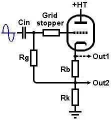
Good job man, you got the topology correct so now let's configure the LND150 to be AC coupled cathode follower.

From Merlin's site:

accf1.jpg


Do you have any idea what your B+2 will be? These values should work OK either way I think:

Rg = 1M
Rb = 680R
Rk = 100k (1W rating)
Grid Stopper = 1k-10k (whatever you have on hand)

And I think coupling between V1A and the LND150 could be as small as 470pF (rated 600VDC+)

And then you want to feed the tone stack from Out2.

Put that together let's see what you got.
 

Dbsoundman

TDPRI Member
Joined
Dec 10, 2014
Posts
74
Location
Maumee OH
B+2 will be 290V per RR’s plans.

I’ll read Merlins site closer to see if I agree with your conclusions. I’m constantly distracted by a 9 month old so admittedly I forgot about that link...
 

Dbsoundman

TDPRI Member
Joined
Dec 10, 2014
Posts
74
Location
Maumee OH
These values should work OK either way I think:

Rg = 1M
Rb = 680R
Rk = 100k (1W rating)
Grid Stopper = 1k-10k (whatever you have on hand)

And I think coupling between V1A and the LND150 could be as small as 470pF (rated 600VDC+)

I read Merlins article, and my only point of contention is Rg. He mentions that Rg is “bootstrapped”, so whereas you might normally need 1M there, 470k is actually sufficient.
 

sds1

Friend of Leo's
Joined
May 4, 2017
Posts
3,274
Location
GA, USA
I read Merlins article, and my only point of contention is Rg. He mentions that Rg is “bootstrapped”, so whereas you might normally need 1M there, 470k is actually sufficient.
Agreed, but the very next thing he points out is the CR filter created by Rg and the input capacitor. With Rg=1M for the same cutoff frequency you can use half the input capacitance compared to Rg=470k. I went for the smaller cap (for real estate purposes only), but like he says 470K is fine too just be aware of its interaction (high-pass filter) with the input capacitor.
 
Last edited:

Dbsoundman

TDPRI Member
Joined
Dec 10, 2014
Posts
74
Location
Maumee OH
Agreed, but the very next thing he points out is the CR filter created by Rg and the input capacitor. With Rg=1M for the same cutoff frequency you can use half the input capacitance compared to Rg=470k. I went for the smaller cap (for real estate purposes only), but like he says 470K is fine too just be aware of its interaction (high-pass filter) with the input capacitor.

I’m not seeing where he says that exactly, can you give me the quote?
 
Top