markeyd123
Tele-Meister
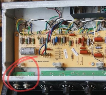
An input jack on my 68 Custom Princeton Reverb reissue is shot, and needs to be replaced for a second time. I want to ditch the PCB mounted plastic jacks and put Switchcraft 12A shunted jacks to replace both of them.
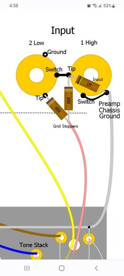
Does anyone know how they would be wired together. I took a look at the PR wiring diagram from @robrob 's site,
.
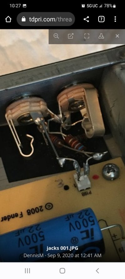
Ultimately I'd like to wire up something along those lines then tie them into the circuit where the existing ones tie in.
Does anyone have a wiring diagram like that I could use, or suggest modifications to the attached one?
Thanks
Does anyone know how they would be wired together. I took a look at the PR wiring diagram from @robrob 's site,
.
Ultimately I'd like to wire up something along those lines then tie them into the circuit where the existing ones tie in.
Does anyone have a wiring diagram like that I could use, or suggest modifications to the attached one?
Thanks
Attachments
Last edited: