Mojotone 5F11 Tremolo problem

  • Thread starter MojoRick
  • Start date
  • This site may earn a commission from merchant affiliate links like Ebay, Amazon, and others.

MojoRick

TDPRI Member
Joined
Aug 9, 2025
Posts
16
Age
78
Location
Merritt Island Florida
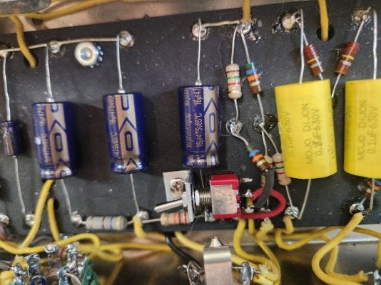
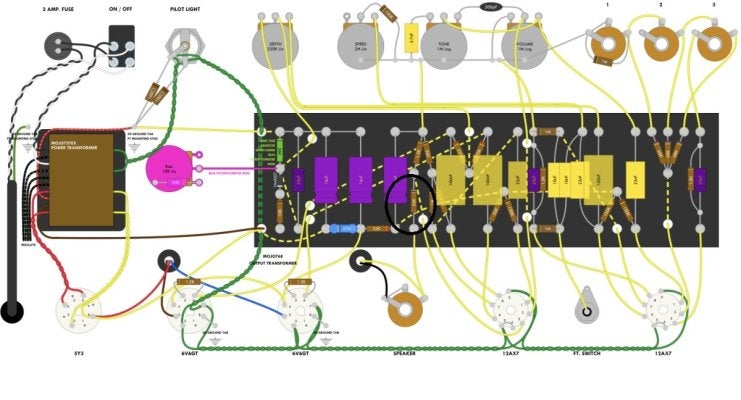
Just completed construction of the 5f11 Mojotone and everything looks solid, Only problem is when the trem is switched on I get a chirping sound with each cycle of the tremolo. I have done the bias mod which doesn't help, in fact it seems to slightly increase the chirp with increasing the bias pot's resistance. Putting the 56K resistor back in (I have installed a switch to select) decreases the chirp a little further, but still present.
Mojotone tech has indicated that this may be a bias problem, and I have measured bias current, which is 24.56 ma for V3 and 27.36 for V4.
Mojo tech has stopped corresponding-
I have borrowed a complete set of tubes, will start by replacing the 6V6's.
If anyone has any assistance to offer I would greatly appreciate.
 

Uffepungen

Tele-Meister
Joined
Jul 20, 2020
Posts
393
Age
35
Location
Sweden
Are you talking about the "ticking" sound?

Do a search for "tremolo diode" mod, I did it on my homebrew 5F11 and it reduced the ticking.

A side note, the ticking is low enough now that I don't worry about it anymore. But I can still "force" it to appear, by increasing the speed and/or depth enough, especially while playing with the volume cranked. I don't know why I can't get rid of it completely. On my homebuilt Princeton Reverb there is no ticking whatsoever.
 

Peegoo

Telefied
Ad Free Member
Joined
Oct 11, 2019
Posts
31,576
Location
Beast of Bourbon
@MojoRick

Lead dress matters because parallel conductors in the tremolo circuit can cause oscillation. Look here:


I grew up on Merritt Island (South Courtenay Parkway). Went to Tropical Elementary School!
 

Mongo Park

Tele-Afflicted
Joined
Nov 28, 2010
Posts
1,750
Location
Winnipeg
I seem to remember that if you add 2 low value caps into the term circuit it fixes it. Maybe someone with a more organized past can add to this as in where they go and what value. I recall 10 nanofared balue for one.
 

King Fan

Doctor of Teleocity
Ad Free Member
Joined
Jan 1, 2013
Posts
12,183
Location
Salt Lake City
Welcome. If this is trem thump, here's the simple fix that worked on my 6G2 (a close cousin to your amp).

1754838533323.png


Here are the 'snubber' caps in the trem circuit -- again, on a 6G2, but the trem circuits are much the same. Our smart friend @theprofessor credits these to Jim Nickelson at Lil Dawg amps. Some folks found one fix worked better than the others; for me, it was the diode, for sure, but if that doesn't help, you could try the snubbers, and if that's not better, I hear some folks even subtract the diode at that point.

1754838832325.png


After we work on the chirp, it'd be good to perfect your biasing so you could restore and fine-tune your bias pot. I'm not sure where or how you're measuring "bias current" -- a confusing term. Is it plate current (good)? cathode current (also good)? or something else?

Anyway, after we're sure you're measuring plate or cathode current, it's also important to measure plate *voltage* at that bias point and calculate actual watts and 'percent of max dispersion'. Rob's calculators and info are a great place to start.

https://robrobinette.com/Tube_Bias_Calculator.htm

We often need to adjust the resistors in the bias-adjust circuit to get the pot to span somewhat above and below 50-70% MPD (say 6 to 8.4 W if we want to be conservative and trem-friendly). If you get this far, let us know what range of *bias voltage* you're getting from your pot. Each tube is different, but here are ranges of 'bias voltage' and 'plate current' for a typical or 'bogie' 6V6 at various plate voltages (credit: @Ten Over ). 'Bias voltage' can be measured usefully at the "220K junction" on your main board.

6V6 bias table HC.jpg
 
Last edited:

MojoRick

TDPRI Member
Joined
Aug 9, 2025
Posts
16
Age
78
Location
Merritt Island Florida
Thanks for all the replies - you guys are awesome.
I'm an ex Air Force radar tech, with my basic electronics training back in the 60s consisting of vacuum tubes exclusively. I haven't seen a tube in 50 years. Building this amp has been fun.
I measured bias current per the following link https://robrobinette.com/How_to_Bias_a_Tube_Amp.htm at the request of Andy, Tech at Mojotone. He has yet to get back to me with optimum values to tune for. Tube dissipations are within nominal safe ranges per this link. Total resistance by the bias mod is set at about 40K ohms in place of the 50K resistor . This setting produces about 38 volts at the junction of the output tubes' 220K grid resistors.
I had my son over today (He's the guitar player) and he noticed that there was also a high frequency squeal being produced that I couldn't hear (My 79 year old ears are bad) - even with no input and trem turned off. Hooking up a scope revealed that it was originating in the second preamp stage.
After moving some wires around to check cross coupling with no change I then removed the feedback resistor from the output jack to the second stage's cathode resistor. With this change the amp seems perfect! Beautiful tone with an ES350 and Tele too. Vibrato fantastic. Amp is very quiet and stable. Gets loud, breakup is perfect at 5-7 volume.
Question is - What bad things happen if I button it up and run it this way? I have checked and rechecked my assembly and can find no mistakes. I love the way it works and sounds in its current state.
Peegoo, small world!
 

King Fan

Doctor of Teleocity
Ad Free Member
Joined
Jan 1, 2013
Posts
12,183
Location
Salt Lake City
Good info. I'm gonna leave the squeal question for other smarter folks. Are you saying your NFB change fixed the bias chirp? Can you tell us or show us (pics rule) what you did to the NFB? Here's the Mojo layout (I like Mojo, but their layouts can be a bit quirky and hard to read).

1754863416365.png


Back at bias, you sound well qualified to do this safely -- and with insight. What're your plate voltages? Looking at the table above, if you're running PV ~400V, then the –38V bias voltage (don't forget the minus) would bias a typical 6V6 to around 70% MPD. But if your PV was 330V (± Fender's 1950s schematic) or even 360V (not atypical in Fender clones), then you'd be biased on the cold side. You can use the table to estimate the bias-voltage range you want to span: at PV 360V for example, you might want to span bias voltages of (roughly) –36 to –30V to span ± 50-70% MPD. This might correspond to plate current range of (nominally) 16.7 to 23.3mA. If I'm reading and thinking right!

BTW, with the power tubes pulled, you can test the full bias-voltage range of your bias pot without risking the tubes. Bias-wiggle amps, as you know, often wiggle best in 45% to 60% range; within our 'safe' range, we really want to tune by ear, not just to some arbitrary voltage or current or MPD figure.

Also, the Mojo bias-adjust circuit is hard to read on their layout. If I'm right, it should look like this. Does yours? IIRC, some Mojo builders have had to change one or the other of the resistors in this circuit to tune their bias range right.

1754863816799.png
 
Last edited:

MojoRick

TDPRI Member
Joined
Aug 9, 2025
Posts
16
Age
78
Location
Merritt Island Florida
Third pic shows the 56K feedback resistor disconnected. 2nd pic shows bias mod with red wires. I put a temporary switch in to be able to return to original setup quickly, will remove and install a fixed resistor when finished tweeking. Sorry about 2,3,4 upside down from the assembly drawing with disconnected 56 K resistor circled.
Like I said, all noise (supersonic whine, clicks, chirps) was eliminated
Looking at the schematic, it appears to me that this feedback path will have very little effect on the V2a, and in fact, RobRob's feedback mod switch in the bottom position removes the feedback loop exactly like I did. I'm sending this amp with the resistor removed.
Noticing that Mojotone's power transformer makes B+ about 15% higher than Fender's original spec, I wonder if eliminating the feedback compensates. Would like to hear you Amp experts' remarks on this.
My son says it's perfect. At some later date I may experiment with the feedback, but probably not. We will evaluate speakers next, but he likes the Jensen C10Q. I will post the finished buttoned up item when I get my custom nameplate installed.
What fun. Love the conversation.
 

Attachments

  • 5F114.jpg
    5F114.jpg
    199.2 KB · Views: 24
  • 5F113[1].jpg
    5F113[1].jpg
    224.3 KB · Views: 24
  • 5F112[1].jpg
    5F112[1].jpg
    233 KB · Views: 23
  • 5F111[1].jpg
    5F111[1].jpg
    261.3 KB · Views: 26
  • 5F11 schematic.jpg
    5F11 schematic.jpg
    275.9 KB · Views: 25
Last edited:

NTC

Friend of Leo's
Joined
Mar 17, 2003
Posts
2,399
Third pic shows the 56K feedback resistor disconnected. 2nd pic shows bias mod with red wires. I put a temporary switch in to be able to return to original setup quickly, will remove and install a fixed resistor when finished tweeking. Sorry about 2,3,4 upside down from the assembly drawing with disconnected 56 K resistor circled.
Like I said, all noise (supersonic whine, clicks, chirps) was eliminated
This sounds like the issue may be that the output transformer phase is wrong. If you are feeling intrepid, reconnect the feedback. Swap the connections of the OT at the output tubes, usually the brown and blue wires. Turn the amp on. It may Squeal (bad, so move the wires back). If it doesn't, run the amp with various settings to see if any obvious oscillation occur. If not, that is the correct wiring.

Edit: @Pete Farrington mentioned this in another thread - did the amp get louder when you disconnected the feedback? It should. If not, you probably have the OT wired backward.

Note there are other ways to accomplish this change.

Running the amp without feedback is not a problem. The famous 5E3 Deluxe has no feedback.
 

MojoRick

TDPRI Member
Joined
Aug 9, 2025
Posts
16
Age
78
Location
Merritt Island Florida
NTC, Will try that! Can't exactly remember loudness before/after but I don't think it got louder. OT is wired per Mojo's diagram.
If reversing OT secondary is effective I will install a switch to turn on/off feedback.
Swapped OT primary wires to reverse of the Mojo assembly drawing and voila! No noise. Put in a switch to turn off feedback. As expected, when feedback switched off there is a slight increase in volume. Son will be back soon with his guitars to evaluate speakers and we will investigate tone with/without feedback. Will update.
When working this switch with power on you must be careful to not touch other stuff in the amp. Ask me how I know.
What an awesome resource you guys are to amateur amp builders. Thanks again.
 

Attachments

  • 20250811_170839.jpg
    20250811_170839.jpg
    207.2 KB · Views: 17

BigDaddy23

Tele-Holic
Joined
Jan 4, 2019
Posts
867
Age
51
Location
Australia
I'm a big fan of NFB defeat switches - Are you planning on putting that switch through the control panel once you've finished testing? You'd have space between the input jacks and the vol pot or between the speaker jack and the first power tube. One small hole and it's done (caveat being those chromed chassis are notoriously hard to drill through). Slow speed, sharp drill with a bit of cutting oil it the way to go.
 

elpico

Tele-Afflicted
Joined
Sep 14, 2011
Posts
1,987
Location
Vancouver BC
When working this switch with power on you must be careful to not touch other stuff in the amp. Ask me how I know.
What an awesome resource you guys are to amateur amp builders. Thanks again.

Uh... I'm sure you already know that's a terrible place for it, so I assume it's temporary for testing and I'll just say use a chop stick to flip it. Do NOT put your fingers in the amp when it's on. Your heart's not 20 anymore.
 

NTC

Friend of Leo's
Joined
Mar 17, 2003
Posts
2,399
Uh... I'm sure you already know that's a terrible place for it, so I assume it's temporary for testing and I'll just say use a chop stick to flip it. Do NOT put your fingers in the amp when it's on. Your heart's not 20 anymore.
And it could kill a 20 year old as well.
 

Jasonpatrick

Friend of Leo's
Joined
May 29, 2022
Posts
2,203
Age
46
Location
Portland Oregon
sounds like you just need to flip the primaries on the OT before doing all the other stuff…


Edit. Ah yep I see that was the prob.
 

King Fan

Doctor of Teleocity
Ad Free Member
Joined
Jan 1, 2013
Posts
12,183
Location
Salt Lake City
It's great you got it fixed; @elpico and @NTC were brilliant to think of this cause, which hadn't occurred to me although lifting the NFB is a classic test for reversed 2° phase. I'll add your symptom (high-pitched whine?) to the list of less-typical PFB symptoms. It's most often a loud squeal, but smart folks say if the oscillation is outside audible range, (or heh, very high), symptoms can be subtle, muffled sound or bad sound or....

BTW, was it the NFB lift that also fixed the chirp in the trem? If so, I can picture that.

OT is wired per Mojo's diagram.

Not your fault -- or theirs, probably. This is one of a dozen things that make early amp builds (and writing instructions, and drawing layouts) complex and confusing. Unless the OT maker marks phase (dots, usually) on the OT schematic, and the layout follows correctly, there's a 50:50 chance you'll get PFB instead of NFB even if you hook up the OT exactly as the poor kit maker draws it. Detailed instructions will often mention lifting NFB if the sound isn't right, but the poor new builder might have to be psychic to know what, when, or how to do it.
 
  • Like
Reactions: NTC

MojoRick

TDPRI Member
Joined
Aug 9, 2025
Posts
16
Age
78
Location
Merritt Island Florida
Uh... I'm sure you already know that's a terrible place for it, so I assume it's temporary for testing and I'll just say use a chop stick to flip it. Do NOT put your fingers in the amp when it's on. Your heart's not 20 anymore.
Uh, yeah. I got a wooden skewer to do that now. If we see a benefit, I will definitely drill a hole and make externally accessable.
It's great you got it fixed; @elpico and @NTC were brilliant to think of this cause, which hadn't occurred to me although lifting the NFB is a classic test for reversed 2° phase. I'll add your symptom (high-pitched whine?) to the list of less-typical PFB symptoms. It's most often a loud squeal, but smart folks say if the oscillation is outside audible range, (or heh, very high), symptoms can be subtle, muffled sound or bad sound or....

BTW, was it the NFB lift that also fixed the chirp in the trem? If so, I can picture that.


Not your fault -- or theirs, probably. This is one of a dozen things that make early amp builds (and writing instructions, and drawing layouts) complex and confusing. Unless the OT maker marks phase (dots, usually) on the OT schematic, and the layout follows correctly, there's a 50:50 chance you'll get PFB instead of NFB even if you hook up the OT exactly as the poor kit maker draws it. Detailed instructions will often mention lifting NFB if the sound isn't right, but the poor new builder might have to be psychic to know what, when, or how to do it.
NFB lift fixed Whine/squeal AND chirp/tick. Corrected OT primary phase enabled restored use of NFB.
I didn't think my ears were so bad - my son said "Really Dad, you can't hear that?" As soon as I knew about it I had grabbed the scope and sig gen, isolated the problem to the second preamp stage and was onto feedback almost right away. The boy was impressed with Pop's troubleshooting prowess.
I think that maybe the kit maker should provide fixes to common problems such as bias- caused and various noises as a little extra sheet included. In fact, Mojo's tech got tired of communicating after 3 emails back and forth. Suggested a bias adjustment but that was about it. I see many builders on this forum have experienced similar problems which could be easily fixed by way of tribal knowledge driven advice. I do understand why Mojo and other kit producers might want keep unskilled solderers and arm's length, however. It takes a lot of patience sometimes to help a needy novice.
 
Last edited:
Top