Making a pedal from an ebay 6j1 kit.

  • Thread starter VintageSG
  • Start date
  • This site may earn a commission from merchant affiliate links like Ebay, Amazon, and others.

VintageSG

Poster Extraordinaire
Joined
Mar 31, 2016
Posts
7,767
Location
Yorkshire
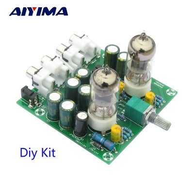
As per the title really. I was bored and browsing Ebay one evening when I came across a preamp kit based around a pair of 6j1 valves.
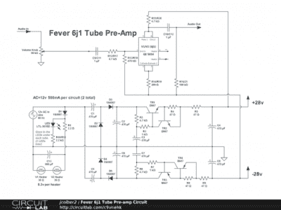
Hmm. Remove the on/off/pot and short out the switch part. Feed the left channel input through a 50K pot ( 50K is what's used on the board ) to set the gain, then take the left channel output and feed it through another pot ( value to be determined by experiment/what I have to hand ) in to the right channel input to set the output gain/level/volume, call it what you will. Basically building another low voltage valve overdrive. These boards take a 12V AC voltage and through on board magic bump it up to 56V ( +/- 28V ) so hopefully it'll be a little less sterile than a 9V or 12V starved plate pedal, while still not being the full 120V the valves would like.
I've got a Behringer VT911 that is to be sacrificed for the cause and it is large enough to house the board and a 12V transformer. It'll also provide the switch. I have a suitable mains switch and inline fuse.
Any obvious flaws in this plan?
6j1.png 6J1-tube-preamp-amplifier.jpg
 

VintageSG

Poster Extraordinaire
Joined
Mar 31, 2016
Posts
7,767
Location
Yorkshire
Part one completed. Build the thing. I didn't bother fitting the blue LEDs under the valve bases as I think they look gash. It went together easily. The component values are printed on the PCB.
The PCB is a thick, rigid, double sided with through plating affair with easy to read silk screening. The components are OK. I struggled t read half the resistor values, but Mr.Multimeter stepped in to save my blushes.
Next, jury rig a transformer and power up.
No popped components, no smoke. Yay!
Next, try it between my CD player and my amp. First, set a reasonable volume level and listen to a song. Next, insert this into the chain and bring the level back up to where it was before. It seems to get 'unity' about halfway through the travel of the pot. Sound wise?, not much difference really. Bring the level up a little higher and the bass is less focussed and cymbals lose a little shimmer. Does it make a CD sound like a 60's radiogram?, nope. Does it sound bad?, nope. Does it improve my CD playing experience?, nope.
Next, connect the 'phone and play a FLAC file. See above.
Next, MP3. Wow!. The zizz and tizz in the upper end that I dislike about MP3 is masked rather nicely. This thing actually does what it's supposed to do!. Colour me surprised. The harsh edge to MP3 is replaced by a woolliness that reduces fatigue. Introduce distortion to reduce fatigue. An interesting idea.
Not what I wanted it for though.
Next, jury rig a couple of cables. Guitar --> right input. Right output --> left input. Left output --> amp. For now, it has the dual gang pot still fitted, so not the best route to sonic nirvana, but it's only early days. When I get round to replace the pot with separate pots, it'll have rather better control. First impressions?, it's a smooth, overdrivey kind of sound. Even wound up full, it doesn't get harsh and bitey. Quite smooth and lush with a pleasant bloom on branged chords. It needs winding up quite high to get the signal going, again, when I get round to using separate pots for gain and output level, that'll change ( I hope! )
Not bad. For £6.58 delivered, not bad at all.

Next job is to get the pots sorted, then replace the mish-mash of butchered cables. Make the transformer safe, enclose the lot and wire a switch up.
 

ukepicker

Friend of Leo's
Joined
Oct 15, 2013
Posts
2,286
Location
Texas
Thanks for sharing this!

It reminds me a bit of the EHX LPB-2UBE pedal I had once. True stereo preamp using two 12xx7 tubes. Really great for warming up solid state amps.

I used mine lots of different ways. But I think my favorite was cascading the gain stages, like how you hooked up your guitar. It had controls for gain (pre) and volume (post) and that made it very versatile. I liked running a 12ax7 in the first stage, hotter than unity, then into a 12au7 to the "edge of breakup" then bring it back down to unity. So many ways to get creative there!

But it's a huge pedal. And noisy. I really like the idea of a small $7 replacement. I'm anxious to see where your further experimentation takes you.
 

VintageSG

Poster Extraordinaire
Joined
Mar 31, 2016
Posts
7,767
Location
Yorkshire
Due to a rookie error on my part measuring the unit up before ordering, I'm in need of an enclosure. Always allow for the height of the PCB standoffs. I failed to. D'Oh! ( slaps forehead )
Slight change of plans may mean it becomes the front end to a full blown amp. It may not, but I couldn't resist one of these.
http://www.ebay.co.uk/itm/291791350601
a £1.54 class D power amp.
The transformer costs will help me decide.
 

Riff Raff

TDPRI Member
Joined
Oct 26, 2017
Posts
3
Age
42
Location
Brazil
Could you post some pictures of the finished wiring?

I bought a pre-amp just like yours and was thinking of just using a p10 stereo jack with a mono plug, but your idea sounds a lot better than mine.

Having a gain stage would make the pedal so much more versatile.

But, since I know nothing about electronics, I’m having a hard time figuring out how you made the connections.

Thanks!
 

VintageSG

Poster Extraordinaire
Joined
Mar 31, 2016
Posts
7,767
Location
Yorkshire
Some pictures.


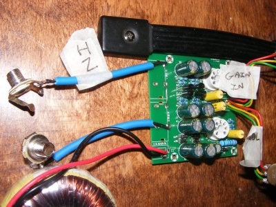
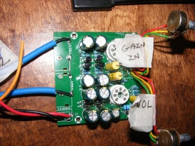
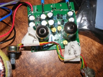
Shows the input at the top, the link between right out and left in ( bare wire linking the phono connector pads, close to the transistors ) and the output, close to the transformer input.
DSCF0629.JPG


DSCF0630.JPG

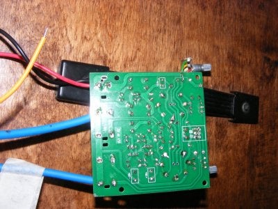
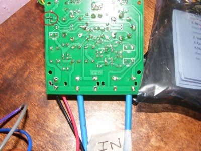
Underside of the board. Nothing much to see here, except top right there is a wire link. Two pads near D1 need linking. This is -NOT- in the instructions, but if you buzz it out, it connects the power in to the switch. Maybe not all boards need it, mine did...

DSCF0631.JPG

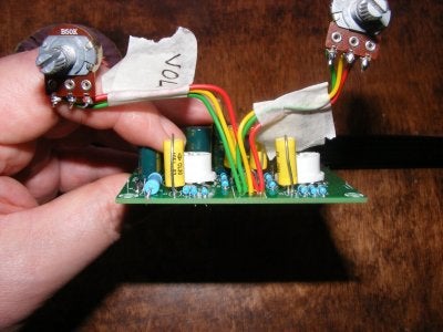
Not exactly clear here. The pot I've marked up as 'Gain' connects to the frontmost set of pads in place of the supplied dual gang. The pot labelled 'Vol' goes to the rearmost set of three pads. I used B50K because that's what I had kicking about. You may want to try audio taper and a higher value for the 'Vol' pot.

DSCF0632.JPG

Just another general top view. It shows where I shorted the power switch behind the control pots. Valves removed for clarity, LEDs not fitted!.

The spurious yellow wire is part of another 12V from the transformer, possibly to be used with an OEP20W Class D mini amp in the future. I'm still looking for a suitable enclosure. As I have it now, it isn't exactly safe.

Hope that helps.
 

Riff Raff

TDPRI Member
Joined
Oct 26, 2017
Posts
3
Age
42
Location
Brazil
That’s awesome! Thanks!

How does it sound with the two pots?

Did you get more overdrive than with the dual gang pot?
 

VintageSG

Poster Extraordinaire
Joined
Mar 31, 2016
Posts
7,767
Location
Yorkshire
By using two pots, it allows the first valve output to be high, which in turn drives the second valve into overdrive/clipping, then you can turn the whole thing down to a suitable level for the input stage of your amp. It also allows you to play about with 'starving' the second valve of signal and winding the volume right up to get the desired output. Both scenarios sound different, both have their uses. One way sounds more 'gainy', the other, more compressed.
It's no different really to the valve pedals that use a 12AX7 and cascade one triode into the other, we're just using two separate triodes.
I've found it doesn't get as gainy sounding as a 12AX7 pedal, but gives a nice, rich bloom and a pleasant growl without fizziness. It can also drive the first valve in the amp into overdrive.
Now I just need an enclosure.

I've played about with an OEP20W micro amp board from Ebay with it. I used an A250K pot between the pre-amp and it and ended up with an amp capable of somewhere around 10 Watts that actually sounds OK.
 

Mike Kaso

TDPRI Member
Joined
Nov 1, 2017
Posts
5
Age
39
Location
Greece
OMG...!!!..!!!!.!! I recently bought a 12ax7 tube to make a kind of distorted preamp. I own a 6j1 kit and I use it as a buffer. Can you please note the wires on the pcb where exactly did you solder them. I can't really figure out from the photos. Sorry for my poor grammar.
 

VintageSG

Poster Extraordinaire
Joined
Mar 31, 2016
Posts
7,767
Location
Yorkshire
DSCF0633.JPG

From the left, the cable labelled 'IN' is connected to what would be the left phono in. The centre ( black in the picture ) connects the tip of the jack socket to the left phono in with the braid connected to the ring of the jack socket and the common ground rail under where the phono connector block would fit.

The wire link between them effectively connects left out to right in. Working from left to right, we have left in, right in, left out, right out, power. You're effectively joining the middle two phono connectors.

DSCF0634.JPG

Underside of the board showing the common ground rail at the lower edge. Power is coming in at the left hand side. The second row up is signal in.

You could use a pair of phono to 6.35mm adaptors and a phono lead. Adaptor in each of the outermost terminals and a phono lead to jumper the innermost pair.

Something like these.
http://www.ebay.co.uk/itm/RCA-Phono...e=STRK:MEBIDX:IT&_trksid=p2060353.m2749.l2649

DSCF0635.JPG

Another view. At the top, you'll see the wire link. This is effectively linking the centre pair of phono terminals ( if you've still got them fitted )
 

Mike Kaso

TDPRI Member
Joined
Nov 1, 2017
Posts
5
Age
39
Location
Greece
mine is not connected here as yours. Should i wire this too?
 

Attachments

  • σσ.jpg
    σσ.jpg
    305.2 KB · Views: 490

VintageSG

Poster Extraordinaire
Joined
Mar 31, 2016
Posts
7,767
Location
Yorkshire
mine is not connected here as yours. Should i wire this too?

No need if it switches on. If you follow the track from the centre pin of your power supply ( uppermost of the power in pads in the picture, red wire connected to it. ) a track leads from there up to a through hole. That wire links the pad across to the switch. I fitted it due to a brainfart on my part. It isn't needed. On the component side, the through holes are linked by a track that passes under D1.

I basically got open circuit when I was following the traces before powering up for the first time so linked it. Turns out I was buzzing a pad coated in lacquer. Oopsie on my part... I was tired. I went down the wrong path. It happens.

I've since built another to eventually use as a buffer and can confirm it isn't needed.

They're quite impressive kits for very little money.
 

Mike Kaso

TDPRI Member
Joined
Nov 1, 2017
Posts
5
Age
39
Location
Greece
Yes indeed el cheapo. I'll go tomorrow for pot hunting. One last thing. Does it needs a logarithmic or linear pot? I'll add a tone pot too.
 

VintageSG

Poster Extraordinaire
Joined
Mar 31, 2016
Posts
7,767
Location
Yorkshire
I'm using B50K for the pots, largely because it's what I had to hand rather than coming to that value from complex calculations. I bought some OEP20W Class D boards and found an A250K gave finer control for the input for that. I'm taking the output connection through the A250K to the OEP. Seems to work just fine.
 

Mike Kaso

TDPRI Member
Joined
Nov 1, 2017
Posts
5
Age
39
Location
Greece
i've just finished it. i've used a 100k pot for volume and 50k for gain. works great but i can't get a totaly clean sound out of it. also i must do something with the gain pot, put a limiter or something cause when it's all the way down i don't get sound at all.
 

nasdak

Tele-Meister
Joined
Mar 22, 2013
Posts
246
Location
france
hello there :)

about the pots :
might be a better idea to place 1st pot between the 2 triodes (where you connected the 2 stages) and the 2nd pot after the 2nd triode ?
 

VintageSG

Poster Extraordinaire
Joined
Mar 31, 2016
Posts
7,767
Location
Yorkshire
It would probably be a very good thing to do. You'll probably need to short out the pads where the pots originally connected.
 
Top