Leslie Project

  • Thread starter keithb7
  • Start date
  • This site may earn a commission from merchant affiliate links like Ebay, Amazon, and others.

keithb7

Poster Extraordinaire
Joined
Jan 9, 2010
Posts
5,701
Location
Western Canada
I hope I am ok to post this thread here. I was asked to take a look at a local musician's Leslie cabinet. It is tube powered somehow. I have never worked on one before, let alone actually play through a Leslie.

I don't quite have a grasp on its function yet. I will be studying as I go through this.

As of this writing I do not know the year. I am sure we will find clues to help get a fairly close date.
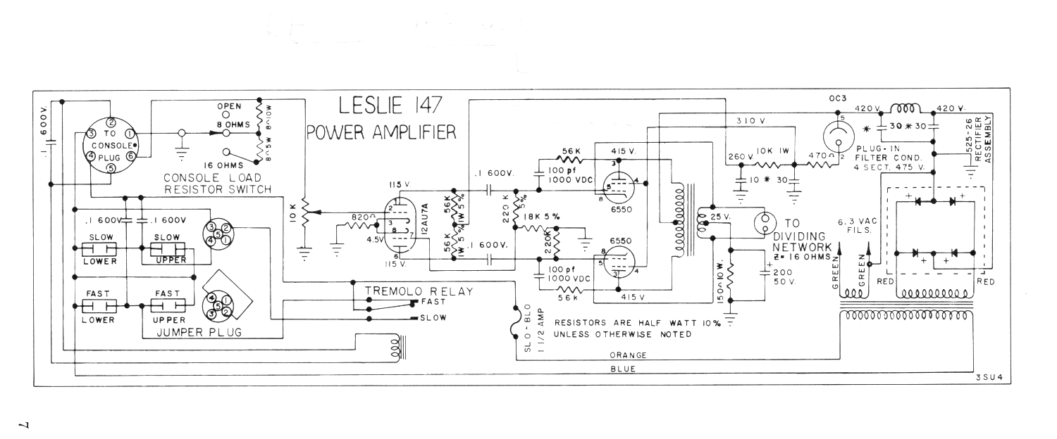
Owner says it is a Leslie 147 from the 60's. I found a schematic on the side of the circuit chassis. It indeed reads "Leslie 147". The C15 Jensen speaker code reads 220742. 42nd week of 1967? Likely.

I'll dig up a schematic and study it a bit.

image removed


image removed


From what I see so far, it appears that the AC power for the Leslie comes from the organ or amp driving it. In this case, the Leslie owner has a Kustom Solid State amp head. It appears to have been modified to work with this leslie. It has a large round 6 pin socket in the rear of the amp, that I see is indeed wired to the Kustom amp's power switch.

Kustom amp seen here:

image removed

Round socket plug for leslie seen below here, top right corner:

image removed

Tubes in this amp appear original and are Leslie brand or RCA. I have not yet figured out how to pull this chassis. The rear 2 mounting screws may have to be pulled blindly?

image removed

More to come as I progress.
 
Last edited:

xafinity

Friend of Leo's
Joined
Dec 24, 2015
Posts
3,910
Location
my Mom's basement
Weird. Hmm. Here's a link to the photo album:

(link removed)

Quit fooling with those photo albums and just drop the j
Jpegs directly into your post
IMG_0084.JPG
 

wanderin kind

Tele-Meister
Joined
Apr 24, 2018
Posts
282
Age
70
Location
Olympia WA
you need the Fender Vibratone. Lucinda William's guitar player was just in here, well, about a year ago, and bought one.

vibratone.png
 

keithb7

Poster Extraordinaire
Joined
Jan 9, 2010
Posts
5,701
Location
Western Canada
You still haven't told us what you are trying to do or fix.

The customer complaint is general intermittent crackling. I was asked to check circuit component values and voltages versus spec. Perform a cap job. Remove fast/slow switch on the Kustom head and replace with a jack that allows control with a footswitch. It'll be slow progress as I put in a little time each evening. I'm questioning myself why I took on this job right now as I am juggling a lot of work around the house. Oh, I remember why now, because owner said I was recommended by a few repeat customers. Hard to let people down.

More info will trickle out as I get into this Leslie further.
 

schmee

Telefied
Ad Free Member
Joined
Jun 2, 2003
Posts
31,222
Location
northwest
I've repaired a couple for my buddy who has 4 now I think... and 5 B3's! Of course the tubes could be the crackling. One died and it turned out to the rectifier diodes.. strange as that doesn't seem to happen much. I replaced them all. Good schems and info on Capn Foldback's site.
 

Hobs

Tele-Meister
Joined
Sep 16, 2011
Posts
303
Location
Nashville, TN
You don't have to pull the rear screws. There's a bracket and a flat hook at the back. Remove the front center screw, then pull straight forward. Easy.
 

moosie

Telefied
Ad Free Member
Joined
Jul 18, 2010
Posts
20,621
Age
68
Location
Western Connecticut
Sounds fantastic!

Footswitch to a relay, eh? Interesting. What's the circuit behind the switch look like?

Not exactly related, but the relay idea made me think of Neil Young and his 'whizzer'.


Snfoilhat

Tele-Afflicted
Joined
Apr 8, 2016
Posts
1,917
Age
44
Location
Oakland, CA
Nice!
I built a Leslie 16/Fender Vibratone type cabinet from an organ's internal Leslie baffle/rotor/motor/speaker assembly, and kicked around a few (bad) ideas for an outboard speed control. I'd also be interested in seeing how this is wired up. Thanks!
 

FenderLover

Poster Extraordinaire
Joined
Jun 11, 2009
Posts
7,073
Location
Minnesota
So, the Kustom drives the Leslie and controls the speed, what does the chassis on the bottom of the cabinet do?
 

keithb7

Poster Extraordinaire
Joined
Jan 9, 2010
Posts
5,701
Location
Western Canada
This whole set up is new to me. So I may not have the facts right, but what I see here is this:

The Leslie chassis has a tube amplifier, as well as a switching device built into it. The main power tubes are 6550 tubes, a pair of 'em. There is a 12AU7 phase inverter and solid state diode rectification. However there is 1 tube that's sole task is a power regulator. There is a 120V switch in the chassis that sets fast or slow speed of the motors that spin the tweeters and the directional scoop under the 15" woofer. This 120V switch is seen in the chassis pic above left of and adjacent to the .1uf green cap. Top right area of the photo.

As far as I can tell, the Kustom is donating a pre-amp signal to the Leslie cab. A heavy duty thick cable connects at the back of the modified Kustom amp that delivers ground, signal, 120V AC mains power, and 120V AC power to the fast/slow switch. The cable connections inside the Kustom go to ground, to the line signal and right off the 120V main power supply. Likely all this would have been much each when you just plugged the Leslie into a Hammond organ that it was designed to be used with. The Leslie cab can do little to nothing on its own. You can't plug a guitar for example directly into it without some type of pre-amp (I think). Anyone feel free to correct me.

When I cycle the fast/slow switch on the face plate of the modified Kustom amp, I am allowing or blocking the secondary 120V AC current to go to that fast/slow switch in the Leslie chassis.

The chassis in the Leslie cab has an ohm load switch for 8 ohm or 16 ohms. Also a volume, which you can crank and get "Born To Be Wild" overdriven organ.
 

keithb7

Poster Extraordinaire
Joined
Jan 9, 2010
Posts
5,701
Location
Western Canada
Nice!
I kicked around a few (bad) ideas for an outboard speed control. I'd also be interested in seeing how this is wired up. Thanks!

Here is a quick illustration of what I was thinking about trying for an outboard speed control. Use a typical hammond smaller chassis box, like used in so many guitar pedals. Install a Carling typical on/off footswitch. Run 9V DC pedal power supply to it. Then run it to a relay inside the Kustom amp that turns off and on 120V AC to the hi/low speed motor inside the Leslie. Sorry about the chicken scratch. Its a crude sketch to illustrate my idea. It is not complete nor accurate but gets the point across I think.

I am open to improvements. Ideas. Or just call me plain dumb. :D - K

image removed
 

moosie

Telefied
Ad Free Member
Joined
Jul 18, 2010
Posts
20,621
Age
68
Location
Western Connecticut
I'm struggling with why a simple fast/slow switch inside the kustom is wall voltage. I know nothing, but that just seems odd. Before hacking up a relay, perhaps explore if the switching circuit is itself a poor hack, that could be done an easier way / lower voltage / ground shorted footswitch. Does that make any sense at all? :lol:
 

keithb7

Poster Extraordinaire
Joined
Jan 9, 2010
Posts
5,701
Location
Western Canada
See the trem fast/slow here in the schematic. Just below the 12AU7. I called this 12AU7 a PI. Actually no, I think it is a pre-amp. No?

leslie147.gif
 
Top