Is there agreement on a safe, simple VVR circuit?

  • Thread starter woodandglue
  • Start date
  • This site may earn a commission from merchant affiliate links like Ebay, Amazon, and others.

woodandglue

Tele-Meister
Joined
Apr 14, 2020
Posts
133
Location
right here
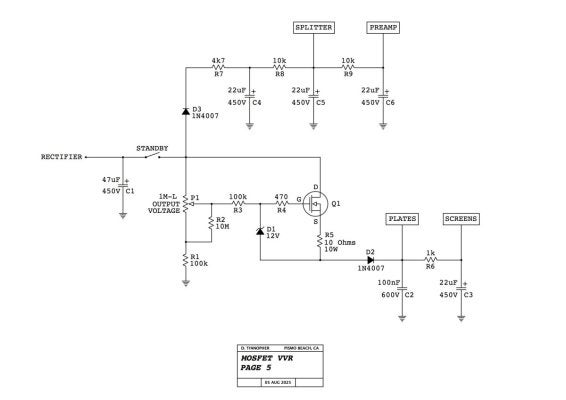
I'm thinking about using VVR circuit (on the power tubes' plates and screens) in a future build, but I am not seeing many schematic examples as I search the web. Please post a circuit have you used, explain why they should be avoided, or something else to better inform me and this community. Thanks!
 

woodandglue

Tele-Meister
Joined
Apr 14, 2020
Posts
133
Location
right here
Excellent resource here:

Thanks Sds1! That is a thorough source. I'm not up to speed on Mosfets and especially how to decide if one is a proper substitution and none of the mentioned ones in that link are available from Antique Electronic Supply, where I'm putting together an order. You've done plenty, but It'd be greatly appreciated if someone in the know would pipe up.
 

Crowe Baaah

Tele-Holic
Gold Supporter
Joined
Aug 11, 2024
Posts
562
Age
44
Location
PA
I'm thinking about using VVR circuit (on the power tubes' plates and screens) in a future build, but I am not seeing many schematic examples as I search the web. Please post a circuit have you used, explain why they should be avoided, or something else to better inform me and this community. Thanks!

Also interested in learning and following along...
 

2L man

Friend of Leo's
Joined
Nov 23, 2020
Posts
4,693
Age
65
Location
Finland
VVR require only few components and is easy to construct without printed circuit board to potentiometer lugs and MosFet legs. Capacitor(s) can be tied drilling four holes and its legs can be used as well. MosFet must have enough gooling so aluminum heat sink is needed if HV is made possible to lower a lot.

Basically there are two kind circuits. One which regulate HV output where potentiometer is set so it is "stiff". Other circuit drop voltage what potentiometer is adjust so it sag what PS allow. More sag come installing series resistor(s)
 

sds1

Friend of Leo's
Joined
May 4, 2017
Posts
3,274
Location
GA, USA
Thanks Sds1! That is a thorough source. I'm not up to speed on Mosfets and especially how to decide if one is a proper substitution and none of the mentioned ones in that link are available from Antique Electronic Supply, where I'm putting together an order. You've done plenty, but It'd be greatly appreciated if someone in the know would pipe up.
You're welcome. Those MOSFET's are end of life and AES doesn't have a great selection anyhow, you'll need to take a trip to Mouser for these. Let's see what we can find...

NTE2973 -- N-Channel, Enhancement Mode, Vdss=900, Vgs=30, Id=14A, Rds(on)=0.63Ω, Pd=275W
STW15NK90Z looks like a great substitute:

NTE2372 -- P-Channel, Enhancement Mode, Vdss=200, Vgs=20, Id=3.5A, Rds(on)=1.5Ω, Pd=40W
IRF9620PBF looks like a great substitute:

Also as @2L man notes you will need to heatsink the power MOSFET (STW15NK90Z) which if space allows it only makes sense to use the giant heatsink you already have (chassis), in this case you'll need to electrically isolate the case from the chassis using the proper thermal insulator which you can find here:

Or if space doesn't allow you can alternatively mount the power MOSFET to its own heatsink using thermal paste (heatsinks for TO-247 package at above link, thermal paste you can get at Mouser too, or on Amazon if you want)

PS the power MOSFET is expensive but if you can swing it I recommend you buy 2 of everything in case you burn something up ;) it sucks to have to pay for shipping again just to get one replacement!
 
Last edited:

chas.wahl

Tele-Holic
Joined
Dec 8, 2012
Posts
977
Location
NYC
One source for both NTE 2973 and NTE 2372 that still exists (NOS) is eBay.

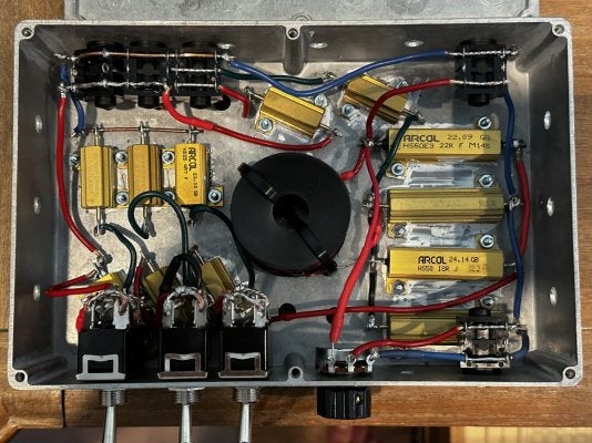
As I understand it, the whole VVR thing is about attenuation, in the end, is it not? An approach that doesn't involve (active, digital) semiconductors is the resistor/inductor-based attenuator, downstream of the output jack. There's a very popular DIY version of one designed by one JohnH from NSW Australia, and published on the Marshall Forum:
It has a fairly large following, and that thread is currently up to nearly 250 pages.
 

Crowe Baaah

Tele-Holic
Gold Supporter
Joined
Aug 11, 2024
Posts
562
Age
44
Location
PA
An approach that doesn't involve (active, digital) semiconductors is the resistor/inductor-based attenuator, downstream of the output jack. There's a very popular DIY version of one designed by one JohnH from NSW Australia, and published on the Marshall Forum:
It has a fairly large following, and that thread is currently up to nearly 250 pages.

Built this as my first DIY project. Bit of an ugly duckling but sounds amazing…

IMG_2123.jpeg
 

sds1

Friend of Leo's
Joined
May 4, 2017
Posts
3,274
Location
GA, USA
One source for both NTE 2973 and NTE 2372 that still exists (NOS) is eBay.
Wouldn't recommend this.

- 2x price of current production
- risk of counterfeit parts
- no point to having these exact part numbers when viable substitutions are easily acquired
 
Last edited:

ievans

Tele-Meister
Joined
Jul 8, 2009
Posts
379
Age
50
Location
Sucka Free, CA
The mosfets are not in the signal chain, so it’s not digitally attenuating the sound of the amp.

The main argument for VVR instead of attenuators is that it’s more efficient. You’re not running the amp at full power and then throwing away most of the output. The main argument against VVR is that it’s not the sound of a cranked amp with saturated tubes and OT.
 

printer2

Doctor of Teleocity
Joined
May 24, 2010
Posts
11,418
Location
Canada
The mosfets are not in the signal chain, so it’s not digitally attenuating the sound of the amp.

The main argument for VVR instead of attenuators is that it’s more efficient. You’re not running the amp at full power and then throwing away most of the output. The main argument against VVR is that it’s not the sound of a cranked amp with saturated tubes and OT.
The Mosfet is in the signal chain, adjusting it changes how the amp operates and modifies the signal.
 

Ten Over

Friend of Leo's
Joined
May 13, 2015
Posts
2,001
Location
Central California
I'm thinking about using VVR circuit (on the power tubes' plates and screens) in a future build, but I am not seeing many schematic examples as I search the web. Please post a circuit have you used, explain why they should be avoided, or something else to better inform me and this community. Thanks!
Is this future build going to be cathode-biased or fixed-biased?
 

ievans

Tele-Meister
Joined
Jul 8, 2009
Posts
379
Age
50
Location
Sucka Free, CA
The Mosfet is in the signal chain, adjusting it changes how the amp operates and modifies the signal.
I would not e.g. consider a dropping resistor in the B+ part of the signal chain. A VVR is more akin to that than a low or high pass filter.
 

printer2

Doctor of Teleocity
Joined
May 24, 2010
Posts
11,418
Location
Canada
I would not e.g. consider a dropping resistor in the B+ part of the signal chain. A VVR is more akin to that than a low or high pass filter.
A stiff PS will make an amp sound differently than one that sags. At low levels you may not hear any difference between them but cranked you would. The same goes with an amp with a VVR. At low levels you man not hear much of a difference but crank it and you will. If you did not know what circuit is in the amp and the VVR control is called something exotic like 'saturation' you might have a hard time deciding if it was in the signal chain or not.
 

woodandglue

Tele-Meister
Joined
Apr 14, 2020
Posts
133
Location
right here
One source for both NTE 2973 and NTE 2372 that still exists (NOS) is eBay.

As I understand it, the whole VVR thing is about attenuation, in the end, is it not? An approach that doesn't involve (active, digital) semiconductors is the resistor/inductor-based attenuator, downstream of the output jack. There's a very popular DIY version of one designed by one JohnH from NSW Australia, and published on the Marshall Forum:
It has a fairly large following, and that thread is currently up to nearly 250 pages.
I like how so far this thread has made it reasonable to be not totally decided on any one way of solving the problems that I create.
 

2L man

Friend of Leo's
Joined
Nov 23, 2020
Posts
4,693
Age
65
Location
Finland
I don't remember seeing VVR circuit which has both "regulated and sagging" outputs but they should be possible to make switchable depending where switch connect potentiometer "reference". Regulated output reference to 0V and sagging reference to output?
 
Top