HS wiring with a 5 way switch

  • Thread starter Steak Knife Sally
  • Start date
  • This site may earn a commission from merchant affiliate links like Ebay, Amazon, and others.

Steak Knife Sally

TDPRI Member
Joined
Sep 14, 2018
Posts
27
Age
59
Location
Minneapolis
I would like to wire my HS guitar with a five way switch. There was a thread on TDPRI which I had bookmarked, but my bookmarks are gone and I can't find the post. The idea was to get the single coil alone, the humbucker alone, the single + Humbucker, the single plus the humbucker split and the humbucker split.

The prior thread started that it couldn't be done. Then someone did it but the picture disappeared. Someone reposted it. At some point Deaf Eddie weighed in.

Finally sat down with the guitar and a soldering iron, but I can't find the saved wiring diagram. Frustrated as heck.

In a perfect world, the diagram would have a single vol and tone.
 

Steve Holt

Friend of Leo's
Joined
May 29, 2016
Posts
4,542
Age
36
Location
Kansas
Well I'm here to say that it could be done easily with a super switch... but I'm not sure how to do it with a regular switch. I'll think about it and get back if no else beats me to it.
 

Steak Knife Sally

TDPRI Member
Joined
Sep 14, 2018
Posts
27
Age
59
Location
Minneapolis
I use Schaller Megaswitch M for 5-ways including HS. Well worth the extra money & easily fits in the cavity.

Scroll down to the various HS configurations. Just Google them & grab for the lowest price.
Looks like the M is mainly about putting the pickups in series. The guitar in question is a Yamaha RGX series. The pickups are a Kiesel AP11 at the neck (around 4k) and a Kiesel M22SD (around 12k) at the bridge. I am more interested in putting the split bridge in parallel with the neck than putting them in series.

The M22SD came to me with a H22 which is a brilliant neck pickup in my Yamaha AES 420, paired with a GFS Mean 90. Beautiful open neck and a bridge like a hottish tele. Hoping for lightning to strike twice. The RGX is pointy and purple, but the neck is fantastic if I can get some less metal sounds from it
 

Tuxedo Poly

Friend of Leo's
Joined
Dec 19, 2011
Posts
2,727
Location
Merseyside UK
Humbucker bridge or neck?
The Fender US Fat Tele is neck HB with those switching options.
 
Last edited:

pipthepilot

Tele-Meister
Joined
Nov 22, 2022
Posts
370
Location
Winchester, UK
I would like to wire my HS guitar with a five way switch. There was a thread on TDPRI which I had bookmarked, but my bookmarks are gone and I can't find the post. The idea was to get the single coil alone, the humbucker alone, the single + Humbucker, the single plus the humbucker split and the humbucker split.

The prior thread started that it couldn't be done. Then someone did it but the picture disappeared. Someone reposted it. At some point Deaf Eddie weighed in.

Finally sat down with the guitar and a soldering iron, but I can't find the saved wiring diagram. Frustrated as heck.

In a perfect world, the diagram would have a single vol and tone.
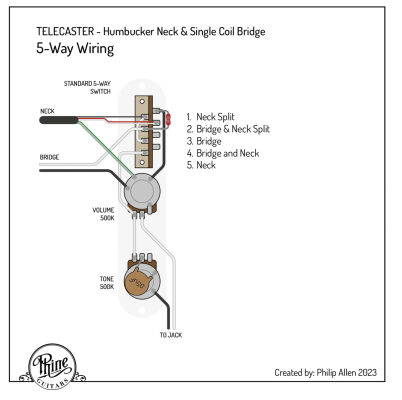
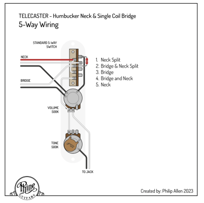
I was about to post it can't be done with a standard 5-way switch and explain why and then I realised if you put the Bridge in the middle position it is possible so here you go. :cool:


Screenshot 2023-03-04 at 21.23.13.png

I've used Seymour Duncan wiring colours for the Humbucker so black is North Start (hot) and White is North Finish (Ground), Red is South Finish (hot) and Green South start (Ground) and the grey is the plate ground. Also, this diagram assumes the two pots are ground connected via the control plate.
 
Last edited:

Steak Knife Sally

TDPRI Member
Joined
Sep 14, 2018
Posts
27
Age
59
Location
Minneapolis
I was about to post it can't be done with a standard 5-way switch and explain why and then I realised if you put the Bridge in the middle position it is possible so here you go. :cool:


View attachment 1091899

I've used Seymour Duncan wiring colours for the Humbucker so black is North Start (hot) and White is North Finish (Ground), Red is South Finish (hot) and Green South start (Ground) and the grey is the plate ground. Also, this diagram assumes the two pots are ground connected via the control plate.
Eureka! Extra credit: does this work with a three wire humbucker?
 

pipthepilot

Tele-Meister
Joined
Nov 22, 2022
Posts
370
Location
Winchester, UK
I think it does, with the pickup’s center tap wire following the grey path, right?
It depends on what type of 3 wire Humbucker you have because not all Humbuckers can be split.

Normally you can’t coil split a 2-wire or 3-wire Humbucker because you need two hot wires. Typically, a 3-wire humbucker has one hot, one ground and one plate ground. If your 3 wire PU has a two hot wires and a common ground/plate ground then it will work.

If you post a pic or your pickup showing the wires I might be able to help.
 

eallen

Friend of Leo's
Joined
Jul 30, 2013
Posts
4,344
Location
Bargersville/Indianapolis, Indiana
Sounds like the Megaswitch E+ may be more in line. They are just showing common options so once you understand how they work you can also make your own adaptations. Just scroll to whatever pup combo you are thinking and you can scroll through the options.
Many humbuckers require a 4 wire for splits.

 
Last edited:

Steak Knife Sally

TDPRI Member
Joined
Sep 14, 2018
Posts
27
Age
59
Location
Minneapolis
It depends on what type of 3 wire Humbucker you have because not all Humbuckers can be split.

Normally you can’t coil split a 2-wire or 3-wire Humbucker because you need two hot wires. Typically, a 3-wire humbucker has one hot, one ground and one plate ground. If your 3 wire PU has a two hot wires and a common ground/plate ground then it will work.

If you post a pic or your pickup showing the wires I might be able to help.

All Carvin 22 series pickups have three wires plus a bare shield wire. The shield wire always goes to ground. The white wire only gets used if you want dual-to-single coil switching. If you don’t want to use this feature, then tape the white wire back. The black and red wires are to be used for standard humbucking operation. Solder red to hot and black to ground. If your guitar sounds out of phase with both pickups on, reverse the red and black wires of one pickup.

So says Carvin
 

pipthepilot

Tele-Meister
Joined
Nov 22, 2022
Posts
370
Location
Winchester, UK
All Carvin 22 series pickups have three wires plus a bare shield wire. The shield wire always goes to ground. The white wire only gets used if you want dual-to-single coil switching. If you don’t want to use this feature, then tape the white wire back. The black and red wires are to be used for standard humbucking operation. Solder red to hot and black to ground. If your guitar sounds out of phase with both pickups on, reverse the red and black wires of one pickup.

So says Carvin
I'm not familiar with Carvin 22 pickups so I had to google it so I understood how they're wired. In the process I realised that I made a mistake with my original diagram.

When I was working this this out, I kept thinking about how Strats are wired. The thinking being a HB and Single coil equals 3 total coils the same as a strat. The problem was, I then wired the switch as if they were three coils is parallel (doh!).

Anyway, here's the correct diagram for you with the Carvin 22 pickup wires. I've also updated the original diagram to the correct one in case someone wants to use it in the future with a Seymour Duncan type wire.

Screenshot 2023-03-04 at 21.22.11.png

So the red wire is the Hot, the black is the ground and the white wire is the join wire between the two coils, when white is grounded, the coil is split, hence the need for a ground wire from the right-side common pin. At least this makes adding the resistor easier.

This was actually an easier schematic to work out, or at least easy enough to work out after a bottle of white wine on a Saturday night :cool:

When you've wired it all up, let me know because I'm always interested to know how it goes.
 
Last edited:

Steak Knife Sally

TDPRI Member
Joined
Sep 14, 2018
Posts
27
Age
59
Location
Minneapolis
Thank you for your help. It will be at least a couple weeks before I can get back to my workshop at the farm, but I will let you know. 250k resister? 500k pots?
 

pipthepilot

Tele-Meister
Joined
Nov 22, 2022
Posts
370
Location
Winchester, UK
Thank you for your help. It will be at least a couple weeks before I can get back to my workshop at the farm, but I will let you know. 250k resister? 500k pots?
If you use a 500k pot you can use a 470k resister so bridge will see the 500k pot as 250k pot. You don't actually need the resister at all but you may find the Bridge pickup is far too bright without it.
 

Tuxedo Poly

Friend of Leo's
Joined
Dec 19, 2011
Posts
2,727
Location
Merseyside UK
If you want a more conventional switching arrangement this is based on the Fender US Fat Tele and assumes the neck pickup is the Carvin M22. The switches are generally available and not much more cost than a standard 5 way.
Tele_SH_Fender_US_Fat_Full_mod.jpg
 

Steak Knife Sally

TDPRI Member
Joined
Sep 14, 2018
Posts
27
Age
59
Location
Minneapolis

The original thread
 

pipthepilot

Tele-Meister
Joined
Nov 22, 2022
Posts
370
Location
Winchester, UK

The original thread
That's actually really interesting. The OP of that thread worked it out in a different way to mine whilst one of the posters lower down worked it out the same as me. The diagram the OP posted, which although a bit weird, is perfectly understandable but I understand why some people wouldn't get it so I'll redraw it and post.
 

pipthepilot

Tele-Meister
Joined
Nov 22, 2022
Posts
370
Location
Winchester, UK

The original thread
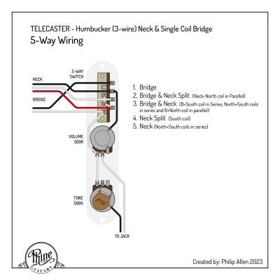
This took a little while to get my head around because it's not a simple circuit to understand and the results of the switching are a little more nuanced than just B, B+N Split, B+N, N Split, N.

For example, the middle position is really funky! You have Bridge and Full Humbucker, but the North coil of the Humbucker is in parallel to the bridge and the South coil is in series with the bridge. 🤯

I'm really curious how this will sound so I'm going to build this circuit myself at the weekend :cool:

PG_logoAsset 7@2x-100.jpg

I've left the resistor off because I haven't worked out yet how the resistor would affect this circuit or if a resistor is the best solution here. I'll probably just end up experimenting to find the best solution for balancing the PUs.
 
Top