
This is from my How Tube Amps Work webpage. As always I'd appreciate corrections and feedback.
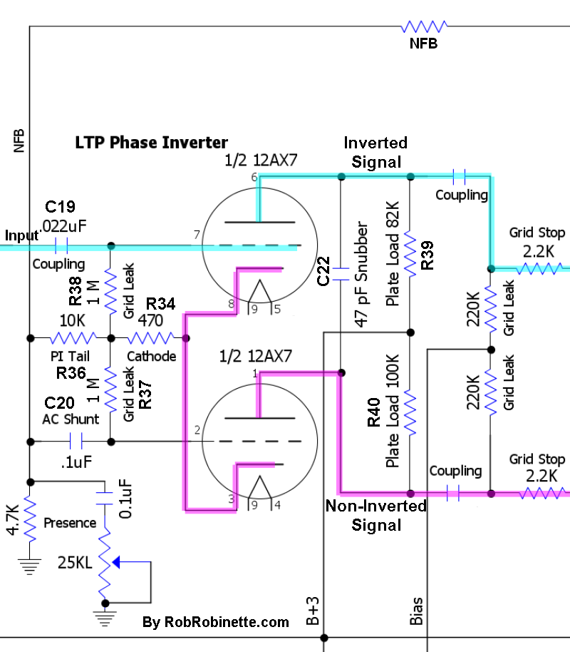
Signal flow shown with red arrows. The Signal enters the phase inverter at V3A's grid and flows out both its plate (inverted signal) and cathode (non-inverted signal). The cathode signal flows to V3B's cathode where it is amplified.
The Long Tail Pair (LTP) Phase Inverter is the most popular phase inverter in guitar amplifiers. Unlike the non-amplifying cathodyne phase inverter it not only creates a dual mirror image signal stream but it also acts as a gain stage boosting the signal by about half of what a normal triode gain stage would do. The LTP is a true differential amplifier and uses both halves of a triode (usually a 12AX7).
Input signal goes to V3A's grid, V3B's grid is held at a constant voltage and capacitor C20 removes all AC signal. Since the grid is held constant voltage fluctuations on the cathode create an amplified signal on V3B's plate.
V3A acts as a normal gain stage (outputs inverted signal at the plate). V3A also acts as a cathode follower (outputs non-inverted signal at its cathode).
V3A and V3B's cathodes are tied together--all of V3B's input signal comes from V3A's cathode.
R34 is the bias resistor and creates the voltage difference between both tubes' grid and cathode.
R36 is the tail resistor that creates the relatively high voltage needed for the cathode follower function of V3A.
R37 and R38 are simply grid leak resistors.
The Presence control (R35 and C21) removes a variable amount of high frequency from Negative Feedback therefore boosting high frequency output (C21 shunts AC signal to ground).
Function Detail: When a positive voltage signal arrives at V3A's grid the reduction of blocking negative electrons on the grid allows electrons to flow from its cathode, through the grid, to its plate. The electrons flowing onto the plate decrease the voltage in the wire between the load resistor and plate--this is the inverted and amplified output signal. As electrons leave V3A's cathode a positive voltage is created on the cathode (scarcity of electrons = positive voltage). This positive signal voltage is also present in V3B's cathode because the cathodes are directly connected. Since V3B's grid is held constant at ground or 0 volts any change in its cathode voltage will create an amplified signal at its plate. As V3B's cathode goes positive (scarcity of electrons) fewer electrons will flow from it through the grid to the plate. The reduction of electrons flowing onto the plate increase the voltage in the wire between the load resistor and plate--this is the non-inverted and amplified output signal.
Bassman 5F6-A LTP PI Voltages
Note the 1.5v bias difference between the tail resistor junction of 32.5v and the cathodes at 34v.
")
