High Voltage Tube Driven Overdrive Pedal Builderino

  • Thread starter kleydejong
  • Start date
  • This site may earn a commission from merchant affiliate links like Ebay, Amazon, and others.

kleydejong

Tele-Holic
Joined
Aug 30, 2010
Posts
930
Location
Orange City, IA
Introduction

Hello friends, I'd like to start a new project. I haven't built an amp from scratch since 2022 - so about 3 years... Sad days. Part of the problem is I've been so happy with the fleet of amps I have, I just don't really have space or need for more. I haven't really wanted to get into building amps to sell for various reasons. So I just haven't...

All that is about to change though! I have been mulling on this project for about 7 years now. I started a thread here:

https://www.tdpri.com/threads/tube-driven-overdrive-preamp-pedal.795272/


That was back in 2018! I got a lot of great feedback. My initial intention is to adapt inspiration from the Kingsley line of high voltage tube driven pedals. But I got a bit intimidated by a few elements of that build. Mostly making a DC power supply that would play nicely with a typical guitar pedalboard power supply. There is a lot of great information in that thread worth reading.

But I'm going to press forward with this build. I'm considering this a prototype. I'm going to intentionally keep things simple and basic. I most likely will iterate on this more in the future.

Design Goals

I want to make a high voltage tube driven overdrive pedal. I want to run it on a pedalboard. I want to run it into the front end of a tube amplifier. I want it to be low to medium gain. I want it to be simple and toneful.

For the power supply I'm going to stay in a safe place and use a 120 vac IEC type power supply input. I'll run it into a fuse - switch. Then into a small Hammond power transformer mounted INSIDE the enclosure. We'll rectify the B+ with diodes. Then smooth it with some filter caps and a step down resistor. Then run two simple 12AX7 gain stages for the audio signal. Gain and Level controls. Maybe some very simple tone filtering. No tone stacks or any shenanigans like that.

Circuit

I have been drawing a schematic in Eagle to mess around with and this is where I'm at currently.

54279481497_98962e7979_o.png


And a layout:

54280603009_6a99cdf63f_o.png


The power supply is incomplete because I don't really know how to do those components in Eagle. I usually just copy a layout from an old Fender that I know well anyways.

Pretty straightforward. I'm thinking a switched cathode bypass cap on V1A will tighten bass going from 10 uf (full frequency) to .68uf (tighter). Then I would like to try Rob's Sizzle control which basically takes a bright cap around the gain pot. Introduce a pot to add resistance to reduce the bright cap. Then once you go past half way on the pot you introduce a dulling circuit. Hoping this setup has less insertion loss, yet provides some tone shaping.

I see a lot of people making more of a 'preamp' where you basically copy a well known preamp design. That doesn't really make sense to me as an overdrive pedal. I want an EQ section that compliments being run into an amp with a tone stack, not duplicates it.

One other element to mention is that I believe Kingsley's drive pedals would add a solid state boost circuit to the input to drive V1A. My circuit would only use V1A to boost the signal into V1B to introduce distortion. So I may later consider adding a very small one knob boost circuit to the input.

Parts

I thought a lot about enclosure and I think the Hammond 1590E will work. It is rather large at about 7" x 4" x 3".

https://www.amplifiedparts.com/products/chassis-box-hammond-1590e-diecast-740-x-472-x-307

I think the height and length will be nice as I want to enclose the transformer and the 12AX7 internally. I also want to build on a turret board so I can access the components reasonably well. I've done some very tight PTP work and in the long run it is hard to work on.

Next Hammond has the 261E6 and Hammond 262E6 transformers which look good for this project. The 261E6 has a 250 vac secondary while the 262E6 has a 120 vac secondary. I actually have one of each, so we'll see. My first reaction is that the 120 vac secondary would be too low, but on second glance it might be pretty cool.

My research says you can estimate your voltage by taking the AC RMS voltage times 1.41 to give you max DC voltage. So 120 * 1.41 = 169 vdc. I think that could work. Might try to draw the load lines and see what I see.

Here is my first layout:

54279508312_c82bb3d820_o.jpg


Time to drill some holes in the chassis!
 

2L man

Friend of Leo's
Joined
Nov 23, 2020
Posts
4,694
Age
65
Location
Finland
To avoid mains "ground loop" I would isolate signal from the metal box which is connect to Safety Earth!

Two double triodes use perhaps only 5mA. If you install for example 20mA secondary HV fuse and 470 ohm resistor between Signal Reference" it will begin to blow the fuse if current leak elevate the signal reference voltage over 10V. Two 20V zener circuit would make this current leak protection double good :) Often also one 100nF capacitor is used to "short" the RF noise.
 

Guerilla Electro

Tele-Holic
Joined
Sep 27, 2023
Posts
714
Age
46
Location
France
Link to EHX English muffin schematic

Do you know the EHX English Muffin , it has 2 12AX7 and is more of a overdrive than a preamp , they run off 12Volts AC 1000 mA adapter , they run at 257 Volts internally . It's a really good circuit , very Marshall-y .
Here's a video showing all the voltages :


Another brand that has interesting tube overdrive designs is SushiBox , although they are specialised in preamps emulations , they have some nice 1 tube overdrive designs.

Nathan at Sushibox FX has put a HV voltage bleed on his pedals , so it drains to safe voltages within seconds when you unplug it ( some run up to 500V internally ).


Sushibox Black eye ( D.i.Y ) (click to zoom on the picture ) :
more info at PedalPCB/Sushibox : link to PdalPCB forums
sushibox-fx-soldano-supercharger-gto-v0-jepla5u77yka1.jpg
 
Last edited:

Guerilla Electro

Tele-Holic
Joined
Sep 27, 2023
Posts
714
Age
46
Location
France
Mostly making a DC power supply that would play nicely with a typical guitar pedalboard power supply.

good to see you reconsidered this aspect of the project as you need more mA than a typical pedal power bricks provides : 100 to 500mA .

You want to fit two 12AX-7 in this box ? you need to cut some vents , it's going to get hot in there !

you may still need some extra circuitry for input and output buffering , for impedance matching ....
 

kleydejong

Tele-Holic
Joined
Aug 30, 2010
Posts
930
Location
Orange City, IA
Here are some schematics I found online re the Kingsley pedals. These may be very inaccurate.

Here is the Page. Single 12AX7. No boost in front of V1A. Pretty simple. Not that far off from what I have.

kingsley page_.JPG


And here are two for the Harlot. Adds a solid state booster in front of V1A.

Kingsley Harlot schemtic.jpg


Kingsley Harlot schemtic 2.jpg


I've noticed they have grid stopping resistors between the two 12AX7 stages. I will add that to my schematic.
 

kleydejong

Tele-Holic
Joined
Aug 30, 2010
Posts
930
Location
Orange City, IA
Further documentation, I also found a PCB for a DIY high voltage power supply.


NTC

Friend of Leo's
Joined
Mar 17, 2003
Posts
2,399
Then I would like to try Rob's Sizzle control which basically takes a bright cap around the gain pot. Introduce a pot to add resistance to reduce the bright cap. Then once you go past half way on the pot you introduce a dulling circuit.
That is basically a tweed-style single knob tone control with a 75k ohm resistor in series with it. Should work like that tone control but with a minimum "muddy" setpoint that won't get as dark as, say, a 5F2A Princeton.
 

kleydejong

Tele-Holic
Joined
Aug 30, 2010
Posts
930
Location
Orange City, IA
To avoid mains "ground loop" I would isolate signal from the metal box which is connect to Safety Earth!

Two double triodes use perhaps only 5mA. If you install for example 20mA secondary HV fuse and 470 ohm resistor between Signal Reference" it will begin to blow the fuse if current leak elevate the signal reference voltage over 10V. Two 20V zener circuit would make this current leak protection double good :) Often also one 100nF capacitor is used to "short" the RF noise.

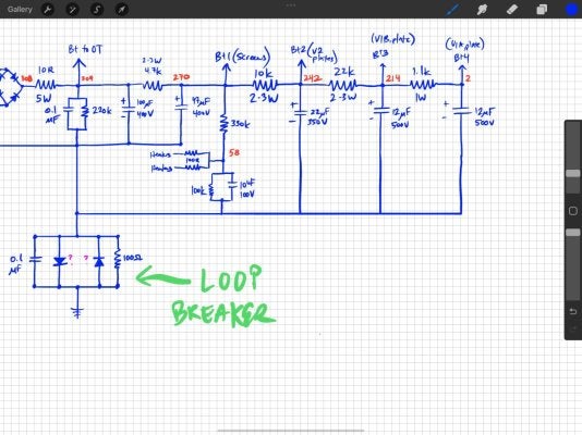
Helpful thoughts. By isolation are you referring to something like this:

1737669164667.png


Source - http://www.valvewizard.co.uk/Grounding.pdf chapter 15.10

I haven't incorporated this into my design, but I will keep it in mind if I have problems with hum.
 

kleydejong

Tele-Holic
Joined
Aug 30, 2010
Posts
930
Location
Orange City, IA
good to see you reconsidered this aspect of the project as you need more mA than a typical pedal power bricks provides : 100 to 500mA .

You want to fit two 12AX-7 in this box ? you need to cut some vents , it's going to get hot in there !

you may still need some extra circuitry for input and output buffering , for impedance matching ....

I'm thinking just one 12AX7. I hear you on the heat and have cut some vents in my chassis.

I haven't included anything for buffering. For input impedance I believe the 1M grid leak resistor in the input should produce a fairly high input impedance.

I'm not sure about the output impedance. I'll look into this further.
 

kleydejong

Tele-Holic
Joined
Aug 30, 2010
Posts
930
Location
Orange City, IA
Pay close attention to the series resistors and volume pot value in the output circuit. Compare your design to the others you posted.

Looks like 470k grid stopping resistors and very low value level pots near the end of the circuit. 25k or 50k.

Would the pot value used for the Level control located on the output set the output impedance?
 

Mexitele Blues

Friend of Leo's
Joined
Mar 7, 2018
Posts
2,329
Age
47
Location
Westminster, CO
Looks like 470k grid stopping resistors and very low value level pots near the end of the circuit. 25k or 50k.

Would the pot value used for the Level control located on the output set the output impedance?

Notice the 220K between the plates and the pots. This resistor sets the output impedance for the tube, as well as forms a voltage divider with the pot to set the max output signal.

Just a 25K pot would leave the tube with no load and sound mushy. A 250K pot would provide the output impedance but leave much of its rotation unused.
 

telemnemonics

Telefied
Ad Free Member
Joined
Mar 2, 2010
Posts
42,414
Age
65
Location
Asheville NC
It will be interesting to hear the results.
I’ve had so many tube dirt pedals of all sorts and none end up really useful.
The Sushi Box JC Emerald had promise on paper but really doesn’t deliver.
I do like the Buddha Zen man and the Soldano GTO both dual 12ax7 with the Zen sounding best but it is old and noisy, probably needs new filter caps.
Have THREE Blackstar tube pedals and like the HT dual.
So many though are not as good as favorite SS clippers.

Good luck!
 

2L man

Friend of Leo's
Joined
Nov 23, 2020
Posts
4,694
Age
65
Location
Finland
Helpful thoughts. By isolation are you referring to something like this:

View attachment 1311988

Source - http://www.valvewizard.co.uk/Grounding.pdf chapter 15.10

I haven't incorporated this into my design, but I will keep it in mind if I have problems with hum.
Basically yes! Modern pedal power supplys do not use mains Safety Earth and which have multiple 9V supplys they are isolated each other. Then there is only one Signal Reference in signal chain!

Because metal box must be connect to SE it should be isolated from 0V = SR as much as possible. I have used picture kind circuit in my few amp builds. Obviously in mains powered effect that 10 ohm resistor could be much higher because effect fuse current is low. Zeners should make "connection" much softer/looser as well but they should be connect series and opposite direction because zener voltage is reverse way and thru normal dirention there is normal diode voltage.

When there is instrument cable from effect output to guitar amp input there come solid / hard wired connection to SE.
 

Crowe Baaah

Tele-Holic
Gold Supporter
Joined
Aug 11, 2024
Posts
562
Age
44
Location
PA
Helpful thoughts. By isolation are you referring to something like this:

View attachment 1311988

Source - http://www.valvewizard.co.uk/Grounding.pdf chapter 15.10

I haven't incorporated this into my design, but I will keep it in mind if I have problems with hum.

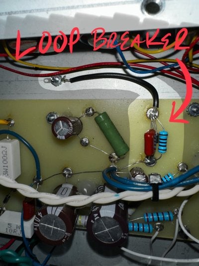
I recently found this little guy while studying the circuit and layout of a custom build I bought some years back, before I took the plunge on building some myself. I couldn’t see the values on the diodes, but the builder had the whole of the ground bus coming to this point.

IMG_1692.jpegIMG_2893.jpeg
 

YellowBoots

Friend of Leo's
Joined
Mar 22, 2020
Posts
3,410
Location
Cincinnati
Would the pot value used for the Level control located on the output set the output impedance?

It would. It would also control the overall level of the output signal, which I assume you would not want to be 100V when the pot is at 100%.

The best you can do without a buffer is make that volume pot value as small as possible. With a 1M pot, you are going to lose tons of high end through cable losses when the volume is not at 100%.
 

2L man

Friend of Leo's
Joined
Nov 23, 2020
Posts
4,694
Age
65
Location
Finland
I recently found this little guy while studying the circuit and layout of a custom build I bought some years back, before I took the plunge on building some myself. I couldn’t see the values on the diodes, but the builder had the whole of the ground bus coming to this point.

View attachment 1312055View attachment 1312056
Diodes current spec should be at least 3x the HV fuse spec! Possibly regulations define voltage spec as well? I have used 1N4007.

Typically resistor is 10R/3W which alone can burn average HV fuse.
 

kleydejong

Tele-Holic
Joined
Aug 30, 2010
Posts
930
Location
Orange City, IA
Some more work on the chassis.

54283900547_0618eeb6fb_o.jpg


I made a bit of a blunder and cut the hole too big for the bass switch. So we're calling it a vent for the 12AX7 on top.

54284789216_e42e866941_o.jpg


54283900517_099ee4f5c0_o.jpg


54283900327_38a2260068_o.jpg


Started working on the power supply. I'm waiting for my turret board to arrive in the mail.

54283900342_635109e5e1_o.jpg


I found a 120vac pilot light which goes in line with the primary side of the PT.

54285035178_6dcf9819b5_o.jpg
 

kleydejong

Tele-Holic
Joined
Aug 30, 2010
Posts
930
Location
Orange City, IA
Updated Schematic given our discussion. Also noticed my PT doesn't have a center tap for the filament winding, so I added a virtual center tap with two 100 ohm resistors.

54285388235_47861a4a01_o.png
 

CoolBlueGlow

Friend of Leo's
Joined
Nov 20, 2011
Posts
2,161
Location
Arkansas
I applaud your pluck. Tube based boost pedals are the road less travelled. :)

But so far, you're basically building a class A amplifier with a couple of gain stages and a basic tone stack in the middle. Nothing wrong with that. But, since you are driving a regular guitar amp, do you really need TWO more gain stages and a tone stack? Your typical guitar amp already has three and its own tone stack, right?

I was going to say why not select a tube that has some diodes in it while you are at it and use them for diode clippers or a kewel tube compressor? But since you've gone this far, maybe that horse is already out of the barn. So maybe ignore my idea? But I was going to suggest a different tube - a ddt, a triode with two diodes in it like the 12AT6 for example. About like a 1/2 of a 12AY7, but with two diodes built into it. Perfectly happy with about 120-160v on the plates. Cheap and easily available too.

Thus the idea of a tube diode based overdrive/distortion pedal. or a tube overdrive with compressor.

Anyway...

Whatever you do, have you thought about using TWO cheap doorbell transformer for your primary transformer? Get a 120/16V and a 120/12V doorbell or similar and wire them secondary to secondary. 120V primary from wall current. Secondary is 16V - Tap, rectify/regulate that 16V down to 12VDC with a 7812 regulator for your tube's DC heaters from there - and also send the unrectified 16V straight into 12V secondary of xformer #2. That turns things around and makes transformer #2's output of was the the "primary" into a secondary. It should make about 160VAC...which you then rectify and filter. That's going to be plenty of current for the plates on a lot of ddt tubes. A 12AT6 only needs 2.5ma to work just fine at those voltages, and should swing about 60 volts-ish.

or... have you thought about using something like a 12AJ6, a high mu triode and double diode that runs on very low plate voltage? They were used in automobile tube radios back in the day. plate voltage is 12vdc. Then a simple 120 to 12V transformer gets you all you need.

But again, you're pretty far down the road as is. Sorry for the flight of fancy.

I ditto what others have said about the grounding scheme, and the ground lifter trick. You're going to need that.
 
Last edited:
Top