
AlexfromGermany
TDPRI Member
Hi,
I saw your YouTube Video and thought maybe I can chime in and see if I could help you with your project.
I didn’t read the all the posts etc. right now.
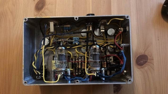
I built a couple of HV Tube Pedals/Preamps in Hammond 1590XX and 1590D enclosures
Kingsley Page
Kingsley Harlot
Mayer Pre
Dumble Pre
Marshall JTM & JCM 800
Fender Bassman
Let me know, if you have any questions.
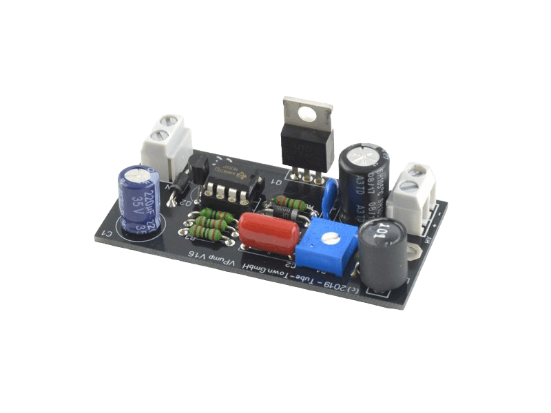
When you really want to save space
Use a SMPS like the
Sushi Box FX HV Daughter
or Tube Town VPUMP
Kingsley / Peace Hill FX etc also use this design for the power supply.
You get 300vdc B+ from 9 or 12vdc in a small package and they are save to use, if you know what you are doing.
I can also send you pictures etc
Hope my English was correct and greetings from Germany,
Alex
I saw your YouTube Video and thought maybe I can chime in and see if I could help you with your project.
I didn’t read the all the posts etc. right now.
I built a couple of HV Tube Pedals/Preamps in Hammond 1590XX and 1590D enclosures
Kingsley Page
Kingsley Harlot
Mayer Pre
Dumble Pre
Marshall JTM & JCM 800
Fender Bassman
Let me know, if you have any questions.
When you really want to save space
Use a SMPS like the
Sushi Box FX HV Daughter
or Tube Town VPUMP
Kingsley / Peace Hill FX etc also use this design for the power supply.
You get 300vdc B+ from 9 or 12vdc in a small package and they are save to use, if you know what you are doing.
I can also send you pictures etc
Hope my English was correct and greetings from Germany,
Alex
Attachments

Last edited:


")


