help with Cabinet Jack Wiring, how to make 1st Jack only speakerA, 2nd Jack is speakersA/B in parallel

  • Thread starter chipstipsforlife
  • Start date
  • This site may earn a commission from merchant affiliate links like Ebay, Amazon, and others.

chipstipsforlife

TDPRI Member
Joined
Mar 19, 2021
Posts
63
Age
47
Location
california
I’ve updated my post and added a drawing as it was pointed out that I was being an idiot.
I apologize.

Let us know what way you end up going with it.
Thank you!
I think I get it.
I use the 12A as Jack1 as the Speaker1 only, with the "shunt" lifted the + doesn't go anywhere.
using Jack2 means the "shunt" is + Tip
 

chipstipsforlife

TDPRI Member
Joined
Mar 19, 2021
Posts
63
Age
47
Location
california
Thank you!
I think I get it.
I use the 12A as Jack1 for Speaker 1 only, because with the "shunt" lifted the + doesn't go anywhere.
using Jack2 means the "shunt" is + Tip, looping in Speaker 2

And I need to use plastic washers to avoid shorting to the Jack plate.
 

A13X

Tele-Meister
Joined
May 20, 2020
Posts
228
Age
40
Location
U.S.A.
Thank you!
I think I get it.
I use the 12A as Jack1 as the Speaker1 only, with the "shunt" lifted the + doesn't go anywhere.
using Jack2 means the "shunt" is + Tip
Exactly. But as others pointed out the TRS option may be the better way to go if you want to use the open jack as an extension. I’ll try and draw it up shortly before I go all crazy on you again.
 

A13X

Tele-Meister
Joined
May 20, 2020
Posts
228
Age
40
Location
U.S.A.
@halfsmith
Here is the TRS drawing
58499998-48E2-4278-97A9-41BAEFA46F16.jpeg

Open jack is extension paralleled with both speakers
Plugging into the TRS uses both speakers by shunting the R/S by way of the T(S) cable jack itself, as the Sleeve makes contact with both the sleeve of the input jack, and the ‘Ring’ connection.

Typically these are used for stereo applications, where the Tip and Ring are used to send left and right speaker signals independently with a TRS cable. In our application, we are just taking advantage of having an extra isolated point to contact the Sleeve of your TS cable.
 
Last edited:

chipstipsforlife

TDPRI Member
Joined
Mar 19, 2021
Posts
63
Age
47
Location
california
Thanks A13X!
Important note, in your TRS diagram the J1/J2 and Sp1/Sp2 positions are opposite (I'd use J2 for 1 speaker, J1 for both)

Assuming your diagrams are correct, you are fully redeemed!

I've been futzing about with this 12A jack all afternoon, but there are already TRS Jacks in the cabinet, so I'll probably just do the TRS style, haha. Glad I waited for clarification.
 

A13X

Tele-Meister
Joined
May 20, 2020
Posts
228
Age
40
Location
U.S.A.
@halfsmith
Yes, i should have specified I placed them that way because it’s looking from the inside out of the cab. When you see them from the back of your cab, The TRS for both speakers will be on the right (jack 2) and the single speaker jack on the left (jack 1), but you can do it whatever you would like…. That said, I think did the diagram with the 12a jack backwards, so how on earth were you supposed know what the heck I was thinking 😂😂
 

Ten Over

Friend of Leo's
Joined
May 13, 2015
Posts
2,001
Location
Central California
I’ve updated my post and added a drawing as it was pointed out that I was being an idiot.
It was most certainly not my intent to characterize you as an idiot. It is abundantly obvious that you are anything but an idiot. Your exemplary desire to help others and your maturity in admitting error are both very impressive, especially in light of the attitude of some folks on these types of forums.

As an example, you have designed a system that achieves what I did in an easier way.
Speaker Jacks A13X.png
 

chipstipsforlife

TDPRI Member
Joined
Mar 19, 2021
Posts
63
Age
47
Location
california
Thanks Ten Over, I appreciate the official schematic symbols, I am now able to read your diagram.

This particular problem causes an error in my brain.
 

chipstipsforlife

TDPRI Member
Joined
Mar 19, 2021
Posts
63
Age
47
Location
california
@halfsmith
Yes, i should have specified I placed them that way because it’s looking from the inside out of the cab. When you see them from the back of your cab, The TRS for both speakers will be on the right (jack 2) and the single speaker jack on the left (jack 1), but you can do it whatever you would like…. That said, I think did the diagram with the 12a jack backwards, so how on earth were you supposed know what the heck I was thinking 😂😂
haha, yeah I don't mean to audit your helpful posts, but I wanted to make sure I understood what I was reading before heating up the soldering iron.
I only meant that from the 12A version to the TRS version, the Jack that does the single vs parallel action swapped places. For my own clarification.
 

A13X

Tele-Meister
Joined
May 20, 2020
Posts
228
Age
40
Location
U.S.A.
@Ten Over
I appreciate your kind words. I’m exceptionally hard on my myself when I make mistakes, particularly when it’s in the context of trying to help someone else.
This community has been there for every question I’ve ever had as I’ve been learning. Without everyone here I certainly would never have gotten to the point of building my own amps and guitars. Turns out I love learning about this stuff. So I’m hoping to give back where I can.

Thanks again!!
 

radiocaster

Doctor of Teleocity
Joined
Aug 18, 2015
Posts
12,013
Location
europe
First jack would need to be a shunt type Switchcraft 12A. Wire the 12" speaker to the tip and ground. Wire the other speakers to the shunt and ground. Second jack would would be a standard Switchcraft 11. Wire the tip to the first jack's tip, and the ground to ground of course. Plugging into the first jack breaks the shunt to tip connection, so the other speakers are disconnected.
This is actually a good method as well. What the 12A does is close a switch when nothing is plugged in. So when nothing is plugged in to the 12" input, the extra lug connects to the tip. The point is so that the tip of the other speaker is disconnected when you plug into the jack of the 12" alone.

A few ways to accomplish this - here is the way I like to do it.

No matter what a Jack (in my example it’s Jack 1) needs a ground shunt like a switchcraft 12a if you want to avoid adding a dedicated switch. Or as mentioned above, a stereo jack (TRS) can be used, this would turn the sleeve of the TS pluged into it a ground shunt between the Ring and Sleeve connection. In that case, the connection to one speaker would be “broken” on the negative side when the trs isn’t used.
Be sure to use isolation washers if mounting to a conductive surface. This way it doesn’t interfere with any scheme you wish to employ.

(Edited as I was corrected by @Ten Over )

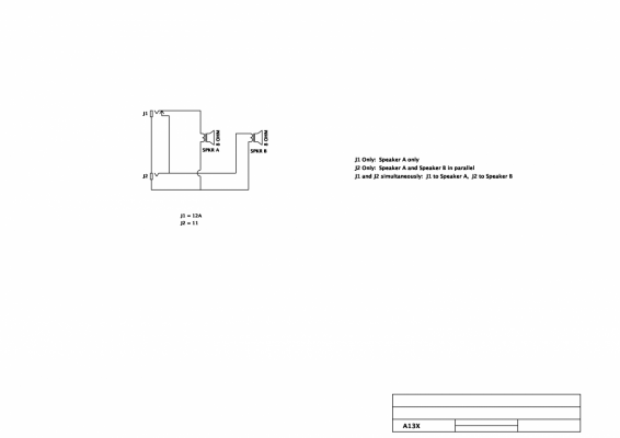
Jack 1 (12a)
tip to (+) of speaker 1 ~
Shunt to tip of Jack 2
Sleeve to (-) of speaker 1
Sleeve to sleeve of jack 2

Jack 2
Tip to (+) of Speaker 2

Speaker 1 (-) to Speaker 2 (-)


When plugged in to J1 only, the tip is lifted off the shunt so speaker 2 gets no (+) it has no path to the second speaker.

When plugged in to jack 2 the shunt of J1 is closed so + makes it to both speakers.

Excuse the barbaric drawing and handwriting.
View attachment 953837

I don’t want to go off of memory again as it was an utter failure this time. I may have used the TRS jack when I wired a cab to use the open jack as an extension jack for an additional speaker in parallel if desired….I think that’s exactly what I did 🤔
This illustrates the 12A method. The 12" alone is on the left, when you plug into it, the switch does not make contact and you don't get the other side.

@halfsmith
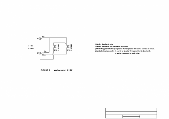
Here is the TRS drawing
View attachment 953844
Open jack is extension paralleled with both speakers
Plugging into the TRS uses both speakers by shunting the R/S by way of the T(S) cable jack itself, as the Sleeve makes contact with both the sleeve of the input jack, and the ‘Ring’ connection.

Typically these are used for stereo applications, where the Tip and Ring are used to send left and right speaker signals independently with a TRS cable. In our application, we are just taking advantage of having an extra isolated point to contact the Sleeve of your TS cable.
This is good as well, except the 12" alone part is on the right in the diagram. This uses a regular stereo jack.

If this is too complicated, you might want to get someone else to do it, as you'll probably botch that network of tweeters and 8" as well.
 

Tim S

Friend of Leo's
Joined
Oct 27, 2008
Posts
2,996
Location
Upstate NY
If you want an off-the-shelf solution, the “Plug and Play” jack plate is about $25 and lets you use either speaker, or both, easily. I built a 2x12 with one and really like it.
I like mine as well. Here’s a diagram of what it does
s-h700_plug_drawing.pdf
 

Ten Over

Friend of Leo's
Joined
May 13, 2015
Posts
2,001
Location
Central California
I've been futzing about with this 12A jack all afternoon, but there are already TRS Jacks in the cabinet, so I'll probably just do the TRS style, haha. Glad I waited for clarification.
When you say TRS jacks, do you mean Switchcraft 12B style or Cliff S2 style?
Littel Jax 12B.png
Cliff Jacks S2.png
 

Ten Over

Friend of Leo's
Joined
May 13, 2015
Posts
2,001
Location
Central California
It looks to me as though there are three viable solutions for the OP that have been suggested:
Speaker Jacks Fig 1 and 2.png
Speaker Jacks Fig 3.png


Figure 2 does what the OP wants, but the two inputs are connected which might present a problem if a stereo power amp is connected using both jacks or if two separate amps are used employing both jacks.

Figure 3 has the same hazard as Figure 2 plus the additional hazards associated with not plugging into J2 fully.

Figure 1 doesn't give the user the opportunity to connect two power amps together and it has the added versatility of functioning as a stereo cabinet. This one gets my vote.
 

chipstipsforlife

TDPRI Member
Joined
Mar 19, 2021
Posts
63
Age
47
Location
california
When you say TRS jacks, do you mean Switchcraft 12B style or Cliff S2 style?
12B style yes.

Figure 3 has the same hazard as Figure 2 plus the additional hazards associated with not plugging into J2 fully.
I went with this arrangement, mostly because it was the least change from what was already in place and it hurts my brain. But I suppose if I go back in there, I will heed your advice and redo it in style 1.
I appreciate the elegance of using the TRS to bridge the gap (with a mono 1/4 plug connecting the R/S pins), I never would have thought of that.
But I do have a 12A jack sitting around that I can swap in.

At the moment, I seem to have the result I was hoping for.
Jack 1 is just the 12", Jack 2 is both sets of speakers.

Thanks great people of TDPRI XD
 

The Ballzz

Friend of Leo's
Joined
Apr 11, 2016
Posts
2,107
Age
70
Location
Las Vegas, NV
The best solution is to use CLIFF style jacks. Once you have them in hand the switching is pretty obvious and it will allow you exactly what you asked for, with the added feature of being able to use the two jacks/speakers separately! Many folks prefer to use the stereo version for more solid support for the plug. Simply ignore the ring connections. CLIFF style jacks actually kick Switchcraft's A$$ in multiple ways! They are automatically isolated, grip the plug better and give a more solid connection to the sleeve. I generally prefer the genuine CLIFF UK units, but the Neutrik/REAN units run a close second.
Just Jackin'
Gene
 
Top