Gibson GA-40 V3 Annotated Schematic

robrob

Poster Extraordinaire
Ad Free Member
Joined
Dec 29, 2012
Posts
8,700
Location
United States
By popular request I annotated one of the more popular Gibson amps, the GA-40 version 3.

image removed
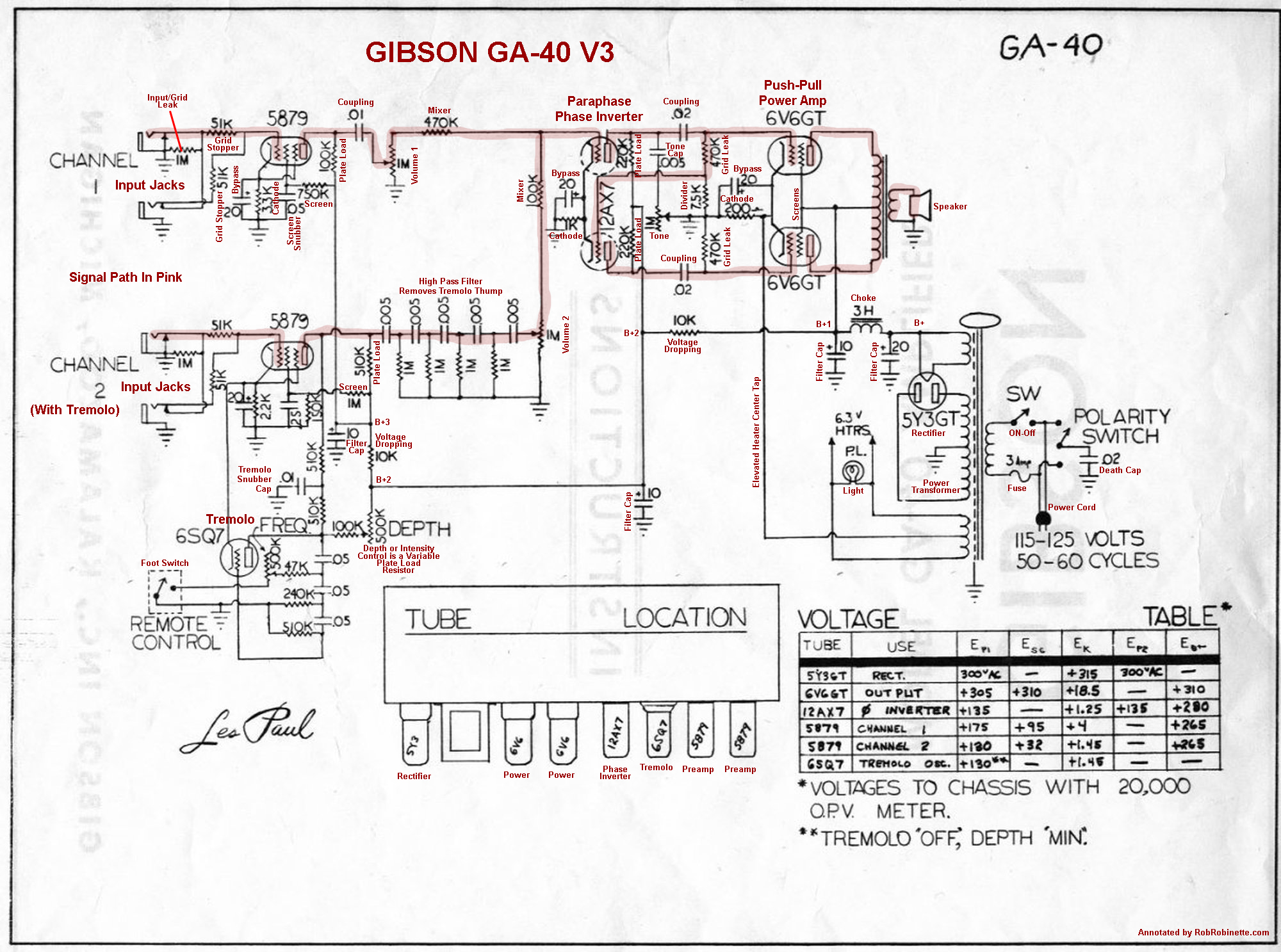
The GA-40 V3 uses one 5879 pentode per channel as a single preamp stage. The paraphase phase inverter lower triode gets its signal to its grid through the upper 470k grid leak resistor. The tremolo oscillation is fed to the channel 2 preamp plate.
 

Bill Moore

Tele-Afflicted
Joined
Feb 2, 2012
Posts
1,665
Location
Silver City, New Mexico
Thank you for that Rob!
I have a '56 that I replaced the P/S caps, but need to probably replace all the others, (behind the board!) Also the trem doesn't work, but other than "breathing", the amp sounds pretty good!
(Pay no attention to the old Utah, it now has a Weber Alnico).

LP2.JPG
 
Last edited:

robrob

Poster Extraordinaire
Ad Free Member
Joined
Dec 29, 2012
Posts
8,700
Location
United States
Nice amp Bill. If you haven't already then try a new 6SQ7 tremolo tube. If that doesn't do it then I'd replace the three .05uF tremolo caps (lower left in schematic) and the .01uF tremolo filter cap. More than likely that will get it going. If you get a tremolo thump then replace the five .005uF caps in the "Tone Filter Network" (center left).
 

Bill Moore

Tele-Afflicted
Joined
Feb 2, 2012
Posts
1,665
Location
Silver City, New Mexico
Thank you Rob!
I figure most of the caps should be replaced, but the board has to come out, and I think it will be a PITA! It had a new trem tube, and the old one in the box in the bottom of the cab when I got it.
 
Last edited:

carlbob

TDPRI Member
Joined
Aug 26, 2020
Posts
10
Location
Texas
Hi Rob, very helpful schematic. Trying to solve a mystery that maybe you could help with. I have the same GA-40 version (cosmetics-wise) that is shown in Bill's photos. My amp follows the attached schematic to a tee. I've been referring to mine as a "series 2" -- based on it being a 1956 and what I see and hear on the Doug and Pat Show where they review these amps. On the D&P video, their series 3 and 4 amps have more gain at lower volume, compared to their series 2 (i.e. my amp). When I change the preamp values of channel 1 (mic) on mine to match your schem, the gain drops. I take it from your schem notation of "v3" it is for a series 3? If so, what might I change on mine, other than the preamp values, to achieve earlier break-up? Thanks for any help on this.
 

Attachments

  • GA-40 schematic.pdf
    612.7 KB · Views: 932

Wally

Telefied
Ad Free Member
Joined
Mar 17, 2003
Posts
46,337
Location
Lubbock, TX
I can no longer see the schematic that Rob showed in post #1. How does it compare to the schematic that you bring to us? .I am looking at that one and one for the GA40 Les Paul at Schematic Heaven. Their input preamps are quite different in these two schematics, so it would be of interest to know what Rob showed us. Do you have that one in your computer so as to share it again?
What are the values of your input signal grid resistors and the cathode resistors in the first stage? Are they as in the schematic you show? fwiw, my inputs are different from both of the schemes have in hand. I have no idea what the cathode resistance is because it is under the board. There is a difference in that area in these two schematics I have, and this amp I have may not match either of those schematics in that area, either!!! thank you Gibson for your lack of continuity, right?
I am wondering if the top panel controls and jacks can be dropped to allow access to the underside of these circuit boards? I also wonder how many hours would be used in doing so...because IF I were to do that, one might want to redo every component on the board. My amp was much used, and I have noted drifted resistors. Ime, once that is seen, there is a lot of work to be done. On an old Fender, that work is right there...easily accessed. Not so on these Gibson amps with components on the underside of the board. They were built to play, and ease of service was not a primary or even secondary consideration, it seems.
I will note that my channel 1 has more gain that does the Trem channel. And...neither channel needs more gain than it has. To manipulate that gain, one could look to the input signal resistance and the cathode resistance of the input preamp. Gibson obviously did look at those areas and put out different versions. To change the cathode resistance and/or bypass capacitance, one would be pulling that circuit board up to access the underside. Labor or love for an owner who is a tech. A labor of hard work and a large repair bill for a good tech. And...one would want to have a very good idea as to what one wanted to do once 9ne got under there....but you have to get under there to know what one has to start with. So, it is hard to know what one would want to do until one sees what one has as a starting point.
i would wonder if you have made up a voltage chart and know your power tube bias numbers.
 

carlbob

TDPRI Member
Joined
Aug 26, 2020
Posts
10
Location
Texas
Wally, I'm attaching Rob's very well annotated schematic. My amp exactly matches the schem I uploaded -- at least in what the components read on my board. Amazingly, the resistors (all of which as you probably know are on top, except for one) measure within spec except for the PI cathode R which I have replaced with 1k as the schem calls for. I bet you are looking at the schematic heaven schem that matches Rob's. That one and the one I uploaded (from another thread here) are the only two I've found.

Yes, it's a pain to get to the underside of the board but releasing the pots and unsoldering the stiff ground wire off Vol 1 pot allows me to peek under more or less. I drew up a layout but at the moment it's chicken scratch that I can barely interpret.

Like I mention, if you want to know my amp's component values, they are on the schem with the 470k input grid stoppers and 3.3M grid leak on channel 1. Rob's has the 51k grid stoppers, 1M grid leak on channel 1. Like yours, my amp's mic channel has more gain than the tremolo channel. Here's my power tube voltages:

screens: 314v
plate: 317v
plate to cathode: 298v
these were with Rk of 1.2 kOhm

The latter series 3 and 4 amps have different schems (i think) but that's what I wanted to check with Rob. I agree with you that the gain on "series 2" is perfect but more so for PAFs not single coils, to my ear anyway. I want to get the gain I hear on Doug and Pat's show when Doug plays the Strat on his series 3 and 4.
 

Attachments

  • Gibson_GA-40_V3_Annotated_Schematic - Robinette.jpg
    Gibson_GA-40_V3_Annotated_Schematic - Robinette.jpg
    207.5 KB · Views: 1,511

Wally

Telefied
Ad Free Member
Joined
Mar 17, 2003
Posts
46,337
Location
Lubbock, TX
Wally, I found Greg's website where he extols the virtues of the GA-40. He accessed the rear by removing the controls, (I'm still dreading getting into mine)!
http://www.gregcutshaw.com/Gibson GA-40 Amp/Gibson GA-40 Amp.html

I have someone's layout from both sides of the board, but I can't find it now, (not that it is the same as either of our amps!) I'll keep looking!

That is how it looked doable to me.


Wally, I'm attaching Rob's very well annotated schematic. My amp exactly matches the schem I uploaded -- at least in what the components read on my board. Amazingly, the resistors (all of which as you probably know are on top, except for one) measure within spec except for the PI cathode R which I have replaced with 1k as the schem calls for. I bet you are looking at the schematic heaven schem that matches Rob's. That one and the one I uploaded (from another thread here) are the only two I've found.

Yes, it's a pain to get to the underside of the board but releasing the pots and unsoldering the stiff ground wire off Vol 1 pot allows me to peek under more or less. I drew up a layout but at the moment it's chicken scratch that I can barely interpret.

Like I mention, if you want to know my amp's component values, they are on the schem with the 470k input grid stoppers and 3.3M grid leak on channel 1. Rob's has the 51k grid stoppers, 1M grid leak on channel 1. Like yours, my amp's mic channel has more gain than the tremolo channel. Here's my power tube voltages:

screens: 314v
plate: 317v
plate to cathode: 298v
these were with Rk of 1.2 kOhm

The latter series 3 and 4 amps have different schems (i think) but that's what I wanted to check with Rob. I agree with you that the gain on "series 2" is perfect but more so for PAFs not single coils, to my ear anyway. I want to get the gain I hear on Doug and Pat's show when Doug plays the Strat on his series 3 and 4.

Thanks for that Carl. I’ll print that one off. That is the same schematic as on Schematic Heaven. My amp has yet again a third set of values for the grid leak and the control grid stoppers....220k and 100k, respectively. I haven’t seen the cathode components under the board. The two schematics I have show different cathode resistances. If It appears that one consistency with old Gibson amps is their inconsistency. It appears that they were searching for different levels of gain in the preamp too, right? I knew an older fellow who had an amp that looked just liked mine except it was mint. He bought it new along with an ES-175. My guess is that he played that guitar amp very regularly for all those years, but never mistreated them. I set his guitar up, but his amp sounded so good that there was no reason for me to say that it needed any work. It was a cleaner amp than mine...later distortion and better articulation. Maybe he had a different input section than did mine???
 
Last edited:

carlbob

TDPRI Member
Joined
Aug 26, 2020
Posts
10
Location
Texas
@Wally, my amp has the 220k grid leak and 100k grid stoppers too, on the tremolo channel. Yours might have the 470k grid stoppers on the mic channel, underneath an s-shaped shield between the two input pairs.
 

Wally

Telefied
Ad Free Member
Joined
Mar 17, 2003
Posts
46,337
Location
Lubbock, TX
@Wally, my amp has the 220k grid leak and 100k grid stoppers too, on the tremolo channel. Yours might have the 470k grid stoppers on the mic channel, underneath an s-shaped shield between the two input pairs.

No, the grid leak and stopper resistors are the same values on both channels in this amp. Like I said, Gibson was consistently inconsistent. It makes me wonder about who wired the amps. If they had been ‘line workers’ who did as they were told and repeated the process, then consistency might have been better.Were the people wiring these amps together actually trained electronic techs who had the freedoms to experiment as they went along??? We will never know, but these two schematics and the comparison of just the input signal of your amp and mine indicate that one might well find anything except a strict adherence to the schematic.
One time I had two Gibson GA35RVTs and one Epi EA16RVT....the same amp with different cosmetics. The three amps were made within weeks of each other, and all were completely original when I got them. Not one of them matched the schematic exactly, and not one of them matched either one of the other two!!! This kind of puts one off one these amps, imho. I have owned a fair number of Gibsons from the BR series of the late Forties through 1966. My favorites have been from 1960-1961. I would really like to have one certain 1960 GA19RVT back. I owned two at the same time....one was dead mint while the other had seen quite a bit of use. The raggedy one was the hot one. Texas fiddler Alvin Crow bought the clean one. A friend owns the raggedy one.
 

Wally

Telefied
Ad Free Member
Joined
Mar 17, 2003
Posts
46,337
Location
Lubbock, TX
Left to right...
EP1...Plate voltage on the first plate..only plate except in the 12AX7 and the rectifier.
ESC....screen grid voltage
EK....cathode voltage
EP2...plate voltage if there is a second plate
The last column is a guess for me.....power supply rail voltage at the OT center tap...
 
Last edited:

Crushtone

NEW MEMBER!
Joined
Jul 7, 2021
Posts
1
Age
64
Location
Atlanta
Greetings All,

I have a mint 1955 GA 40 cosmetically. However the trem does not work. Does anyone have a parts list to recap this thing. I have put a brand new 6SQ7 in it. It changed nothing. Other than trem not working, it is quite and sounds great. I figure the caps on the underside of that board get hotter and go bad quicker than the top. It looks to me that is where the trem circuit is. Any suggestions would be greatly appreciated. @robrob @Wally @carlbob @Bill Moore
 

Wally

Telefied
Ad Free Member
Joined
Mar 17, 2003
Posts
46,337
Location
Lubbock, TX
I am not going to be be much help here. My Les Paul GA40T works great…..and is not in great cosmetic condition. Have you replaced all of the electrolytic capacitors? Are you experienced in amp tech work? If the electrolytics are original, that is where I would start. Here is the schematic….if you are lucky, the amp matches this. Gibson is known for having been fast and lose with changes to the circuit….but not the schematic.
my trem circuit was weak until I replaced the under-sized output transformer someone had put in the amp. I ordered a Mercury Magnetics and Voila! The amp’s sound got bigger and richer, and the trem works at all intensity settings now whereas before the intensity to be way up on the dial. Iirc, there is a trim pot inside the circuit. There is a pot shown in the schematic following the PI. I don’t think it is associated with the trem, though. Could that pot be a balancing act for the paraphase phase inverter?
does the footswitch work properly? I check simple stuff first.
 
Top