Friedman Golden pearl build. Help with first strip board pedal circuit

  • Thread starter ElGuapoTaco
  • Start date
  • This site may earn a commission from merchant affiliate links like Ebay, Amazon, and others.

ElGuapoTaco

TDPRI Member
Joined
Jul 10, 2022
Posts
31
Age
44
Location
North Carolina
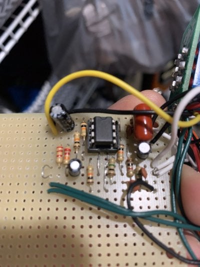
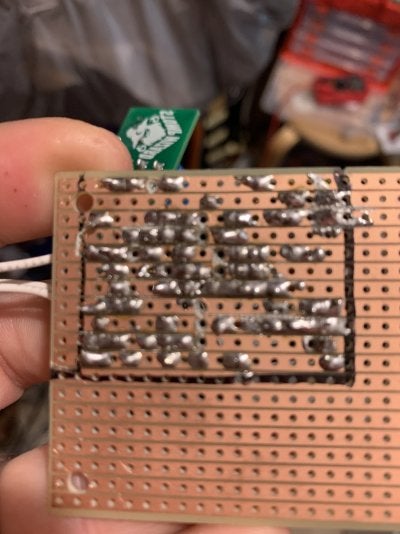
Hi there. Building a Friedman golden pearl OD on strip board. Usually I’m using PCBs so this is a bit new to me. Frustrated because I’m sure I did a messy job but not sure exactly what setting to use on my new multimeter too.

I ran a jumper instead of out to one of the switches for the time being just for testing

Thanks.
 

Attachments

  • image.jpg
    image.jpg
    135.1 KB · Views: 123
  • image.jpg
    image.jpg
    146.8 KB · Views: 116
  • image.jpg
    image.jpg
    179.8 KB · Views: 107

hopdybob

Friend of Leo's
Joined
May 28, 2008
Posts
3,641
Location
netherlands
if i think the soldering went wandering on the next by strip i take a little microsaw and saw down all the lanes and check with a magnifying glass if the lanes are clean.
than connect all the pots and switches with some longer wires and test it if things work.
than, if things work as they should box it in together with trimming the wires etc.
 

ElGuapoTaco

TDPRI Member
Joined
Jul 10, 2022
Posts
31
Age
44
Location
North Carolina
I ran a knife down the tracks and tried to resolder any joints that were cold. I added both switches so everything is complete. Just getting a ground dead silence signal and hum. I’m sure it’s probably my sorry excuse for soldering on strip board for the first time but hey whatever I’m learning
 

Attachments

  • image.jpg
    image.jpg
    131.6 KB · Views: 50

owlexifry

Tele-Meister
Joined
Feb 10, 2021
Posts
482
Location
SA, Australia
- trying using circuit board cleaner, or similar (isopropyl alcohol?) to rinse off all the flux residue and other micro crap that can cause shorts / bridging

- if still no luck, try using an ‘audio probe’.

(this is how i try and find errors in my circuit builds, it happens)

an audio probe can give you a reasonably pinpointed clue about where you might have messed up on the circuit.
1652075679571.png


77817783-ED78-45EA-A90D-299D60E36E07.jpeg

all you need is:
- mono jack (send to an amp / stereo)
- insulated wire+alligator clip (to clip to ground)
- 100nF cap (voltage rating to your application, i used 630V cos the leads are robust and can use on amps)
- audio source to feed the pedal circuit input (guitar, music player, iphone )

what to do:
- feed some constant audio into the input of the pedal circuit being tested (iphone, mp3 player, whatever, use an adaptor etc.)
- with the tip of the probe (capacitor lead), you trace the signal from input, along the circuit board (schematic will help here) until you find where the signal is being lost/muted/weird.

- eg. start with 22nf input cap, then the 1k resistor (that goes to the opamp input), then check if the audio is coming out of the opamp output pin, etc.
- you could also start from the output jack and work backwards,
eg. output jack tip -> volume pot lug 2 -> vol lug 3 -> 10uf output cap. etc.


here’s me trying find where i made an error on an OD-1 build
D8471C49-B2D2-4539-9D03-3B09C61047C7.jpeg

065F9323-4120-4054-A133-DE86B93C1B96.jpeg


good luck ✌🏻
 

ElGuapoTaco

TDPRI Member
Joined
Jul 10, 2022
Posts
31
Age
44
Location
North Carolina
- trying using circuit board cleaner, or similar (isopropyl alcohol?) to rinse off all the flux residue and other micro crap that can cause shorts / bridging

- if still no luck, try using an ‘audio probe’.

(this is how i try and find errors in my circuit builds, it happens)

an audio probe can give you a reasonably pinpointed clue about where you might have messed up on the circuit.
1652075679571.png


View attachment 1018885

all you need is:
- mono jack (send to an amp / stereo)
- insulated wire+alligator clip (to clip to ground)
- 100nF cap (voltage rating to your application, i used 630V cos the leads are robust and can use on amps)
- audio source to feed the pedal circuit input (guitar, music player, iphone )

what to do:
- feed some constant audio into the input of the pedal circuit being tested (iphone, mp3 player, whatever, use an adaptor etc.)
- with the tip of the probe (capacitor lead), you trace the signal from input, along the circuit board (schematic will help here) until you find where the signal is being lost/muted/weird.

- eg. start with 22nf input cap, then the 1k resistor (that goes to the opamp input), then check if the audio is coming out of the opamp output pin, etc.
- you could also start from the output jack and work backwards,
eg. output jack tip -> volume pot lug 2 -> vol lug 3 -> 10uf output cap. etc.


here’s me trying find where i made an error on an OD-1 build
View attachment 1018888
View attachment 1018890


good luck ✌🏻
Wow thank you so much. Pulling my hair out because I am sure the circuit is correct. I will redo the door switch too after cleaning the board and also trying to trace with an audio probe like you suggested. Great advice!
 

hopdybob

Friend of Leo's
Joined
May 28, 2008
Posts
3,641
Location
netherlands
ehhh, i think you made a grand mistake, that i have made to when starting with stripboard


the components are place in reflexion.

look at the position of the opamp and were the 47u can capasitor is placed.
diagram shows right, you placed it left, and other components to.
 

ElGuapoTaco

TDPRI Member
Joined
Jul 10, 2022
Posts
31
Age
44
Location
North Carolina
ehhh, i think you made a grand mistake, that i have made to when starting with stripboard


the components are place in reflexion.

look at the position of the opamp and were the 47u can capasitor is placed.
diagram shows right, you placed it left, and other components to.
I think I’m the pic of the board it is upside down. I’m pretty sure I have everything the right way
 

ElGuapoTaco

TDPRI Member
Joined
Jul 10, 2022
Posts
31
Age
44
Location
North Carolina
i think not, i am sorry
look at the notch at the opamp.
that is in the same position as on the strip board layout, but the red cap is on your picture right on the layout left.
the jumper wires are mirrored to
That’s because the back is reversed from what is shown in the strip board layout picture, as if it were see through
 

ElGuapoTaco

TDPRI Member
Joined
Jul 10, 2022
Posts
31
Age
44
Location
North Carolina
ehhh, i think you made a grand mistake, that i have made to when starting with stripboard


the components are place in reflexion.

look at the position of the opamp and were the 47u can capasitor is placed.
diagram shows right, you placed it left, and other components to.
Yes you are right. Rookie mistake I guess. Didn’t realize the way to read it properly
 

owlexifry

Tele-Meister
Joined
Feb 10, 2021
Posts
482
Location
SA, Australia
Yes you are right. Rookie mistake I guess. Didn’t realize the way to read it properly
we all make mistakes man.

this time, would definitely recommend cutting out the board to size before soldering the components in.


i found this guide helpful when starting out on vero.

all the best! you can do this 💪
 

Greenmachine

Tele-Afflicted
Joined
Nov 28, 2011
Posts
1,732
Location
BC
ehhh, i think you made a grand mistake, that i have made to when starting with stripboard


the components are place in reflexion.

look at the position of the opamp and were the 47u can capasitor is placed.
diagram shows right, you placed it left, and other components to.
I've done this too. Very frustrating.
 

zippofan

Tele-Afflicted
Joined
Mar 16, 2014
Posts
1,933
Location
Pennsylvania
I don't have anything to add that hasn't already been posted by the others in this thread other than the Golden Pearl is a favorite OD. I made FuzzDog's board and it sounds great! Good luck with your rebuild!
 

archtop_fjk

Tele-Afflicted
Joined
Aug 4, 2009
Posts
1,416
Location
New Hampshire
- trying using circuit board cleaner, or similar (isopropyl alcohol?) to rinse off all the flux residue and other micro crap that can cause shorts / bridging

- if still no luck, try using an ‘audio probe’.

(this is how i try and find errors in my circuit builds, it happens)

an audio probe can give you a reasonably pinpointed clue about where you might have messed up on the circuit.
1652075679571.png


View attachment 1018885

all you need is:
- mono jack (send to an amp / stereo)
- insulated wire+alligator clip (to clip to ground)
- 100nF cap (voltage rating to your application, i used 630V cos the leads are robust and can use on amps)
- audio source to feed the pedal circuit input (guitar, music player, iphone )

what to do:
- feed some constant audio into the input of the pedal circuit being tested (iphone, mp3 player, whatever, use an adaptor etc.)
- with the tip of the probe (capacitor lead), you trace the signal from input, along the circuit board (schematic will help here) until you find where the signal is being lost/muted/weird.

- eg. start with 22nf input cap, then the 1k resistor (that goes to the opamp input), then check if the audio is coming out of the opamp output pin, etc.
- you could also start from the output jack and work backwards,
eg. output jack tip -> volume pot lug 2 -> vol lug 3 -> 10uf output cap. etc.


here’s me trying find where i made an error on an OD-1 build
View attachment 1018888
View attachment 1018890


good luck ✌🏻
I love the idea of using the micro amp for audio probe testing on the bench. Thanks for the idea - much easier than using a full size amp!
 

cdwillis

Tele-Meister
Joined
Jan 20, 2010
Posts
269
Location
Indiana
Once I get my vero boards marked, cut, jumpered, and parts populated/soldered, I go back with my multimeter and check continuity among the traces. It only takes a couple minutes and helps troubleshoot in case issues arise later.
 

ahiddentableau

Friend of Leo's
Joined
Jul 8, 2018
Posts
2,290
Location
Middle of Nowhere
Audio probe. Otherwise you're going to be spinning your wheels for hours on end.

Get the probe working. Then ensure that the power supply is working and delivering power where it should be going. Then trace signal until you find where it craps out. Then you have a fighting chance because you know the general area of the problem.
 
Top