optilude24
TDPRI Member
TL;DR: I built a single-channel Deluxe Reverb-style amplifier into an existing Princeton Reverb chassis and cabinet, reusing the transformers, pots, switches, pots, jack, reverb tank and so on, but completely changing the circuit board and tube layout. It uses a 6BM8 tube for the reverb. I think it sounds pretty good! There are schematics and layouts below. Some tone demos here.
Keep reading for the full story! I've had to split this into a few replies to fit within the forum limits.
My first amp build was a Princeton Reverb kit from Modulus Amplification in the UK. The kit is great and eventually worked well, but I had several issues initially that stemmed from my own lack of experience and mediocre soldering skills. A part of me always wanted to go back and clean everything up.
Some time later, after building another kit from Modulus – a Marshall JTM50 “Black Flag” Plexi – with more confidence, I decided I really wanted a Deluxe Reverb style amp. I liked the Princeton but the Deluxe sounded better to me, especially when pushed into overdrive. However, the Deluxe Reverb is physically larger than the Princeton, and I didn’t really have space for one, let alone one more amp.
As I started to study the circuit, I realised that the “vibrato” channel of the Deluxe Reverb is not very different from a Princeton Reverb. After all, the amps were contemporaries in Fender’s “blackface” era, and based on the same circuit design principles. The main differences are:
There are a few other minor circuit differences, including some modifications I had made to the Princeton, such as switchable negative feedback and mid cut and boost EQ controls, but it raised a tantalising question: could I modify the Princeton Reverb into a single-channel Deluxe Reverb by changing the circuit, but reusing the cabinet, speaker, chassis, transformers, reverb pan, filter capacitor can, and so on?
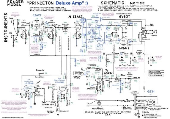
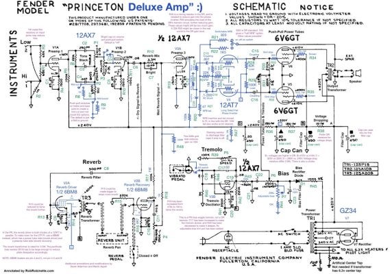
With the help of my amp mentor Derek Alderman, I began thinking through how I’d do this, starting with a Princeton Reverb schematic and modifying it to align to the Deluxe Reverb vibrato channel circuit. After many, many iterations, that looked like this:

I used the drawing software OmniGraffle to add layers to the original Princeton Reverb drawing, hiding certain parts, and drawing new ones (in blue) until the circuit represented my single-channel Deluxe Reverb. You can see my annotations in purple. I have also labelled each resistor and capacitor for ease of identification.
Next, I had to figure out how to lay this out on the circuitboard and in the chassis. But I quickly realised I’d have a problem: the LTP phase inverter uses both triodes in a 12AT7 tube, whereas the Princeton’s cathodyne phase inverter uses just one side of a 12AX7. In other words, I would need an extra half preamp tube. Adding a new tube would require drilling a large new hole in a chassis where space is a premium. This was not very attractive.
Derek provided the solution. Both the Princeton Reverb and Deluxe Reverb use one whole preamp tube (both sides of a 12AT7 in parallel) to drive the spring reverb pan. They do this because driving the reverb pan is a lot like driving a speaker, and it requires a lot of power. But there is another type of tube called a 6BM8. It’s longer than your typical preamp tube, but it packs a pentode (basically a small power tube) and a triode (like one half of a 12AX7) into a single 9-pin valve that will fit into a preamp tube socket. The idea was to use the more powerful pentode side in place of the parallel 12AT7 triodes as a reverb driver, and the triode side as the reverb recovery amplification stage that is normally performed by the first half of the next tube over.
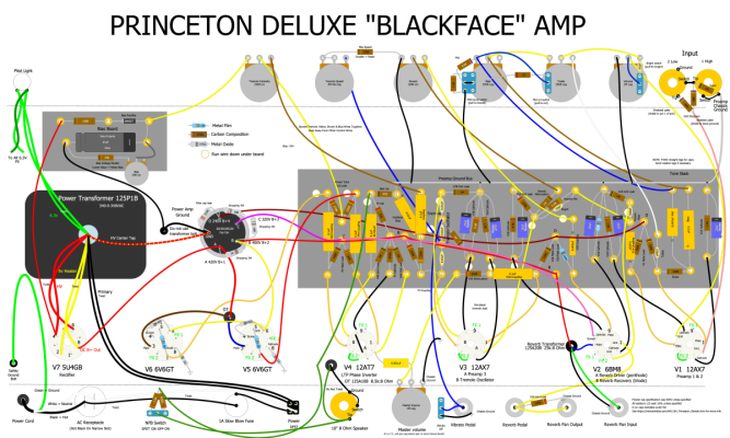
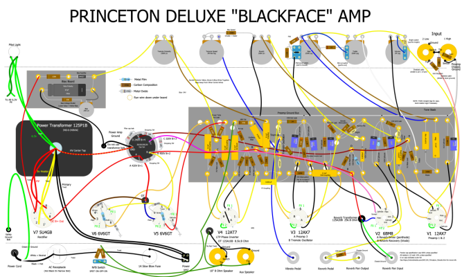
By saving one triode, I could shift each of the other triodes in the preamp “down one”. So a 12AX7 in V1 provides the first two preamp stages, just like in a Princeton. The 6BM8 tube goes in the V2 position, and performs reverb driver and recovery duties. V3 is another 12AX7, the first half acting as the third preamp stage (which was previously on V3B), and the second half providing the oscillator for the Princeton-style tremolo circuit (which used to be V4A). Both sides of V4 are now freed up, and so it can be used for the 12AT7 phase inverter tube.
One remaining concern was power draw. The 6BM8 pentode uses a lot more current than two 12AT7 triodes in parallel, and the Princeton power transformer was not designed with this in mind. I decided to swap my JJ power tubes with some Tung-Sol tubes that in theory have slightly lower power draw. But there would certainly be somewhat lower voltages throughout the amp.
I decided to make some other modifications too, mostly carrying over from the my earlier Princeton build:

You may notice there is no “dog house” with the large B+ filter capacitors you’d see in a Deluxe Reverb. Instead I am reusing the capacitor can that serves the same purpose in the Princeton. There is also no choke. This worked fine and met my goal of reusing as much of the Princeton as possible. Another option might have been to cover the hole for the filter cap can and extend the turret board further to the left to fit full size filter capacitors.
I now had a layout, but it was clear I could not use the same turret board as the Princeton. The preamp stages were pretty similar, but over at the phase inverter end, things had changed quite a lot. I also needed physically more space, as the LTP phase inverter is more involved than the cathodyne one.
For space reasons, I moved the dropping resistors to the filter cap can lugs, and moved various things around to fit everything in and make wire runs as short as possible. It’s worth noting that the position of some of the tube sockets is less optimal for the Deluxe Reverb layout, leading to some slightly longer wire runs, but with some care I was able to avoid any spider webs.
Then I needed to make a circuit board. I decided to stick to turrets, since that’s what I had experience with, but with a new layout, I had to make my own drill template. I ordered fibreglass board and turrets from Modulus, and a cheap “swaging tool” from AliExpress to fix them to the board. I also had to get a drill press - something I’d put off for too long - to be able to drill the turret holes straight and perform the swaging itself. Here’s what the drill template looked like:

This was also drawn in OmniGraffle, using a 1:1 A4 resolution and various hidden guides to get things to line up. The black circles represent areas to install turrets and the white circles represent holes through which I intended to run wires down under the board. I wrote the names of the components that go in each position other help test the layout: before starting the drilling process, I printed the template and physically laid each component on top of it to make sure there was enough space between the turrets.
Next I had to get all the new components: Resistors in various values, capacitors (I went with Orange Drops), that elusive 6BM8 tube, and extra wire. All from Modulus, with tubes from Watford Valves. And a few add-on orders for things I’d forgotten or hadn’t realised I’d need. (The First Rule of Resistors is: No matter how many you have, you are always missing the specific one you need.)
It was then time to start building.
Keep reading for the full story! I've had to split this into a few replies to fit within the forum limits.
My first amp build was a Princeton Reverb kit from Modulus Amplification in the UK. The kit is great and eventually worked well, but I had several issues initially that stemmed from my own lack of experience and mediocre soldering skills. A part of me always wanted to go back and clean everything up.
Some time later, after building another kit from Modulus – a Marshall JTM50 “Black Flag” Plexi – with more confidence, I decided I really wanted a Deluxe Reverb style amp. I liked the Princeton but the Deluxe sounded better to me, especially when pushed into overdrive. However, the Deluxe Reverb is physically larger than the Princeton, and I didn’t really have space for one, let alone one more amp.
As I started to study the circuit, I realised that the “vibrato” channel of the Deluxe Reverb is not very different from a Princeton Reverb. After all, the amps were contemporaries in Fender’s “blackface” era, and based on the same circuit design principles. The main differences are:
- The Deluxe has a Long Tail Pair phase-inverter. The Princeton uses a cathodyne phase inverter. This changes the way the amp breaks up as you crank the volume, and is one of the biggest reasons the tone is different.
- The Princeton uses a “bias wiggle” tremolo design, whereas the Deluxe has a very different design based on an opto-coupler. Many people prefer the Princeton design, and I decided I would try to keep it.
- The Deluxe’s vVibrato channel has a small “bright cap” on the volume control to increase high frequencies at low volume. I have always been a bit dubious about bright caps, so I initially decided to leave it out, but later added it as an option with a push-pull volume knob.
- The amount of negative feedback, which is used to clean up the amp, is different. And it is inserted at a different point in the circuit, which has to do with the LTP phase inverter having gain.
- The Deluxe has a 12” speaker, and the Princeton uses a 10”. It is possible to fit a 12” speaker in a Princeton cabinet (it’s a fairly common Princeton modification), but I tend to use the amp through a cabinet emulator anyway for silent playing, so this was a little academic. I decided to leave my Jensen C10R alone.
There are a few other minor circuit differences, including some modifications I had made to the Princeton, such as switchable negative feedback and mid cut and boost EQ controls, but it raised a tantalising question: could I modify the Princeton Reverb into a single-channel Deluxe Reverb by changing the circuit, but reusing the cabinet, speaker, chassis, transformers, reverb pan, filter capacitor can, and so on?
With the help of my amp mentor Derek Alderman, I began thinking through how I’d do this, starting with a Princeton Reverb schematic and modifying it to align to the Deluxe Reverb vibrato channel circuit. After many, many iterations, that looked like this:
I used the drawing software OmniGraffle to add layers to the original Princeton Reverb drawing, hiding certain parts, and drawing new ones (in blue) until the circuit represented my single-channel Deluxe Reverb. You can see my annotations in purple. I have also labelled each resistor and capacitor for ease of identification.
Next, I had to figure out how to lay this out on the circuitboard and in the chassis. But I quickly realised I’d have a problem: the LTP phase inverter uses both triodes in a 12AT7 tube, whereas the Princeton’s cathodyne phase inverter uses just one side of a 12AX7. In other words, I would need an extra half preamp tube. Adding a new tube would require drilling a large new hole in a chassis where space is a premium. This was not very attractive.
Derek provided the solution. Both the Princeton Reverb and Deluxe Reverb use one whole preamp tube (both sides of a 12AT7 in parallel) to drive the spring reverb pan. They do this because driving the reverb pan is a lot like driving a speaker, and it requires a lot of power. But there is another type of tube called a 6BM8. It’s longer than your typical preamp tube, but it packs a pentode (basically a small power tube) and a triode (like one half of a 12AX7) into a single 9-pin valve that will fit into a preamp tube socket. The idea was to use the more powerful pentode side in place of the parallel 12AT7 triodes as a reverb driver, and the triode side as the reverb recovery amplification stage that is normally performed by the first half of the next tube over.
By saving one triode, I could shift each of the other triodes in the preamp “down one”. So a 12AX7 in V1 provides the first two preamp stages, just like in a Princeton. The 6BM8 tube goes in the V2 position, and performs reverb driver and recovery duties. V3 is another 12AX7, the first half acting as the third preamp stage (which was previously on V3B), and the second half providing the oscillator for the Princeton-style tremolo circuit (which used to be V4A). Both sides of V4 are now freed up, and so it can be used for the 12AT7 phase inverter tube.
One remaining concern was power draw. The 6BM8 pentode uses a lot more current than two 12AT7 triodes in parallel, and the Princeton power transformer was not designed with this in mind. I decided to swap my JJ power tubes with some Tung-Sol tubes that in theory have slightly lower power draw. But there would certainly be somewhat lower voltages throughout the amp.
I decided to make some other modifications too, mostly carrying over from the my earlier Princeton build:
- The volume control has a push-pull pot to engage the “bright cap” that is on the Deluxe Reverb Vibrato channel. The default is to omit the bright cap, but by pulling the volume knob out, I can get something that is even closer to the Deluxe Reverb Vibrato channel.
- Treble and bass controls are also push-pulls, offering an optional “mid cut” on the treble knob and “mid boost” on the bass knob, in lieu of an actual mid control. I had this on the Princeton too, and it’s an easy and largely self-contained modification.
- There are some tweaks to the tremolo circuit to make the tremolo deeper and slower, as suggested by Rob Robinette on his Princeton Reverb pages.
- The power tubes get grid stoppers, screen resistors, and convenience 1 ohm biasing cathode resistors, again as suggested by Rob Robinette.
- A three-way switch at the back allows the amount of negative feedback to be varied. More negative feedback means the amp is cleaner. No negative feedback makes it sound more “tweed-like” and raunchy. This fits into the hole that in the Princeton is used as a “ground lift” switch, also known as the “death cap”. The Modulus kit originally had a dummy switch here: installing this bit of the circuit is not safe. The replacement switch is an SPDT on-off-on switch, and finding one with a ~11mm mounting diameter was surprisingly annoying.
- I added a mini switch next to the “vibrato” foot switch socket that shorts the foot switch wire to ground, in the same way tapping the pedal would. I don’t use (or even own) a foot switch but it’s nice to have a physical way to fully kill the tremolo. Especially, it turns out, when using an oscilloscope to look at certain parts of the amp.
You may notice there is no “dog house” with the large B+ filter capacitors you’d see in a Deluxe Reverb. Instead I am reusing the capacitor can that serves the same purpose in the Princeton. There is also no choke. This worked fine and met my goal of reusing as much of the Princeton as possible. Another option might have been to cover the hole for the filter cap can and extend the turret board further to the left to fit full size filter capacitors.
I now had a layout, but it was clear I could not use the same turret board as the Princeton. The preamp stages were pretty similar, but over at the phase inverter end, things had changed quite a lot. I also needed physically more space, as the LTP phase inverter is more involved than the cathodyne one.
For space reasons, I moved the dropping resistors to the filter cap can lugs, and moved various things around to fit everything in and make wire runs as short as possible. It’s worth noting that the position of some of the tube sockets is less optimal for the Deluxe Reverb layout, leading to some slightly longer wire runs, but with some care I was able to avoid any spider webs.
Then I needed to make a circuit board. I decided to stick to turrets, since that’s what I had experience with, but with a new layout, I had to make my own drill template. I ordered fibreglass board and turrets from Modulus, and a cheap “swaging tool” from AliExpress to fix them to the board. I also had to get a drill press - something I’d put off for too long - to be able to drill the turret holes straight and perform the swaging itself. Here’s what the drill template looked like:
This was also drawn in OmniGraffle, using a 1:1 A4 resolution and various hidden guides to get things to line up. The black circles represent areas to install turrets and the white circles represent holes through which I intended to run wires down under the board. I wrote the names of the components that go in each position other help test the layout: before starting the drilling process, I printed the template and physically laid each component on top of it to make sure there was enough space between the turrets.
Next I had to get all the new components: Resistors in various values, capacitors (I went with Orange Drops), that elusive 6BM8 tube, and extra wire. All from Modulus, with tubes from Watford Valves. And a few add-on orders for things I’d forgotten or hadn’t realised I’d need. (The First Rule of Resistors is: No matter how many you have, you are always missing the specific one you need.)
It was then time to start building.
Last edited:
")