DIY single-channel "Deluxe Reverb" build in a Princeton chassis and cabinet

optilude24

TDPRI Member
Joined
Sep 19, 2023
Posts
22
Age
41
Location
UK
TL;DR: I built a single-channel Deluxe Reverb-style amplifier into an existing Princeton Reverb chassis and cabinet, reusing the transformers, pots, switches, pots, jack, reverb tank and so on, but completely changing the circuit board and tube layout. It uses a 6BM8 tube for the reverb. I think it sounds pretty good! There are schematics and layouts below. Some tone demos here.

Keep reading for the full story! I've had to split this into a few replies to fit within the forum limits.

My first amp build was a Princeton Reverb kit from Modulus Amplification in the UK. The kit is great and eventually worked well, but I had several issues initially that stemmed from my own lack of experience and mediocre soldering skills. A part of me always wanted to go back and clean everything up.

Some time later, after building another kit from Modulus – a Marshall JTM50 “Black Flag” Plexi – with more confidence, I decided I really wanted a Deluxe Reverb style amp. I liked the Princeton but the Deluxe sounded better to me, especially when pushed into overdrive. However, the Deluxe Reverb is physically larger than the Princeton, and I didn’t really have space for one, let alone one more amp.

As I started to study the circuit, I realised that the “vibrato” channel of the Deluxe Reverb is not very different from a Princeton Reverb. After all, the amps were contemporaries in Fender’s “blackface” era, and based on the same circuit design principles. The main differences are:
  • The Deluxe has a Long Tail Pair phase-inverter. The Princeton uses a cathodyne phase inverter. This changes the way the amp breaks up as you crank the volume, and is one of the biggest reasons the tone is different.
  • The Princeton uses a “bias wiggle” tremolo design, whereas the Deluxe has a very different design based on an opto-coupler. Many people prefer the Princeton design, and I decided I would try to keep it.
  • The Deluxe’s vVibrato channel has a small “bright cap” on the volume control to increase high frequencies at low volume. I have always been a bit dubious about bright caps, so I initially decided to leave it out, but later added it as an option with a push-pull volume knob.
  • The amount of negative feedback, which is used to clean up the amp, is different. And it is inserted at a different point in the circuit, which has to do with the LTP phase inverter having gain.
  • The Deluxe has a 12” speaker, and the Princeton uses a 10”. It is possible to fit a 12” speaker in a Princeton cabinet (it’s a fairly common Princeton modification), but I tend to use the amp through a cabinet emulator anyway for silent playing, so this was a little academic. I decided to leave my Jensen C10R alone.
One way to think of it, is that the Vibrato channel of a Deluxe Reverb is akin to a Princeton Reverb with a different tremolo, a Long Tailed Pair (LTP) phase inverter, and a bright cap. Or conversely, that a Princeton Reverb is like a single channel Deluxe Reverb with a bias wiggle tremolo and cathodyne phase inverter.

There are a few other minor circuit differences, including some modifications I had made to the Princeton, such as switchable negative feedback and mid cut and boost EQ controls, but it raised a tantalising question: could I modify the Princeton Reverb into a single-channel Deluxe Reverb by changing the circuit, but reusing the cabinet, speaker, chassis, transformers, reverb pan, filter capacitor can, and so on?

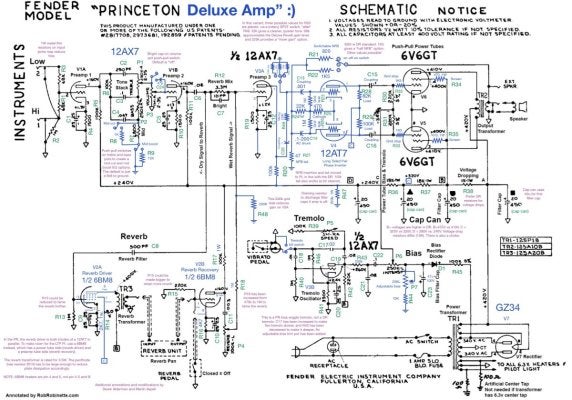
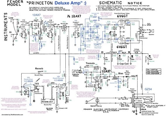
With the help of my amp mentor Derek Alderman, I began thinking through how I’d do this, starting with a Princeton Reverb schematic and modifying it to align to the Deluxe Reverb vibrato channel circuit. After many, many iterations, that looked like this:

IMG_0525.JPG


I used the drawing software OmniGraffle to add layers to the original Princeton Reverb drawing, hiding certain parts, and drawing new ones (in blue) until the circuit represented my single-channel Deluxe Reverb. You can see my annotations in purple. I have also labelled each resistor and capacitor for ease of identification.

Next, I had to figure out how to lay this out on the circuitboard and in the chassis. But I quickly realised I’d have a problem: the LTP phase inverter uses both triodes in a 12AT7 tube, whereas the Princeton’s cathodyne phase inverter uses just one side of a 12AX7. In other words, I would need an extra half preamp tube. Adding a new tube would require drilling a large new hole in a chassis where space is a premium. This was not very attractive.

Derek provided the solution. Both the Princeton Reverb and Deluxe Reverb use one whole preamp tube (both sides of a 12AT7 in parallel) to drive the spring reverb pan. They do this because driving the reverb pan is a lot like driving a speaker, and it requires a lot of power. But there is another type of tube called a 6BM8. It’s longer than your typical preamp tube, but it packs a pentode (basically a small power tube) and a triode (like one half of a 12AX7) into a single 9-pin valve that will fit into a preamp tube socket. The idea was to use the more powerful pentode side in place of the parallel 12AT7 triodes as a reverb driver, and the triode side as the reverb recovery amplification stage that is normally performed by the first half of the next tube over.

By saving one triode, I could shift each of the other triodes in the preamp “down one”. So a 12AX7 in V1 provides the first two preamp stages, just like in a Princeton. The 6BM8 tube goes in the V2 position, and performs reverb driver and recovery duties. V3 is another 12AX7, the first half acting as the third preamp stage (which was previously on V3B), and the second half providing the oscillator for the Princeton-style tremolo circuit (which used to be V4A). Both sides of V4 are now freed up, and so it can be used for the 12AT7 phase inverter tube.

One remaining concern was power draw. The 6BM8 pentode uses a lot more current than two 12AT7 triodes in parallel, and the Princeton power transformer was not designed with this in mind. I decided to swap my JJ power tubes with some Tung-Sol tubes that in theory have slightly lower power draw. But there would certainly be somewhat lower voltages throughout the amp.

I decided to make some other modifications too, mostly carrying over from the my earlier Princeton build:
  • The volume control has a push-pull pot to engage the “bright cap” that is on the Deluxe Reverb Vibrato channel. The default is to omit the bright cap, but by pulling the volume knob out, I can get something that is even closer to the Deluxe Reverb Vibrato channel.
  • Treble and bass controls are also push-pulls, offering an optional “mid cut” on the treble knob and “mid boost” on the bass knob, in lieu of an actual mid control. I had this on the Princeton too, and it’s an easy and largely self-contained modification.
  • There are some tweaks to the tremolo circuit to make the tremolo deeper and slower, as suggested by Rob Robinette on his Princeton Reverb pages.
  • The power tubes get grid stoppers, screen resistors, and convenience 1 ohm biasing cathode resistors, again as suggested by Rob Robinette.
  • A three-way switch at the back allows the amount of negative feedback to be varied. More negative feedback means the amp is cleaner. No negative feedback makes it sound more “tweed-like” and raunchy. This fits into the hole that in the Princeton is used as a “ground lift” switch, also known as the “death cap”. The Modulus kit originally had a dummy switch here: installing this bit of the circuit is not safe. The replacement switch is an SPDT on-off-on switch, and finding one with a ~11mm mounting diameter was surprisingly annoying.
  • I added a mini switch next to the “vibrato” foot switch socket that shorts the foot switch wire to ground, in the same way tapping the pedal would. I don’t use (or even own) a foot switch but it’s nice to have a physical way to fully kill the tremolo. Especially, it turns out, when using an oscilloscope to look at certain parts of the amp.
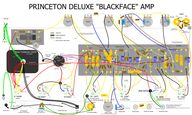
Here is what this layout ended up looking like. I used the DIY Layout Creator software to draw this, starting with Rob Robinette’s Princeton Reverb file and following my schematic. I labelled each component on the schematic and used the same names in the DIYLC file to make it easier to correlate the two, taking plenty of inspiration from the Deluxe Reverb schematic.

Princeton Deluxe v1.0.png


You may notice there is no “dog house” with the large B+ filter capacitors you’d see in a Deluxe Reverb. Instead I am reusing the capacitor can that serves the same purpose in the Princeton. There is also no choke. This worked fine and met my goal of reusing as much of the Princeton as possible. Another option might have been to cover the hole for the filter cap can and extend the turret board further to the left to fit full size filter capacitors.

I now had a layout, but it was clear I could not use the same turret board as the Princeton. The preamp stages were pretty similar, but over at the phase inverter end, things had changed quite a lot. I also needed physically more space, as the LTP phase inverter is more involved than the cathodyne one.

For space reasons, I moved the dropping resistors to the filter cap can lugs, and moved various things around to fit everything in and make wire runs as short as possible. It’s worth noting that the position of some of the tube sockets is less optimal for the Deluxe Reverb layout, leading to some slightly longer wire runs, but with some care I was able to avoid any spider webs.

Then I needed to make a circuit board. I decided to stick to turrets, since that’s what I had experience with, but with a new layout, I had to make my own drill template. I ordered fibreglass board and turrets from Modulus, and a cheap “swaging tool” from AliExpress to fix them to the board. I also had to get a drill press - something I’d put off for too long - to be able to drill the turret holes straight and perform the swaging itself. Here’s what the drill template looked like:

IMG_0512.JPG


This was also drawn in OmniGraffle, using a 1:1 A4 resolution and various hidden guides to get things to line up. The black circles represent areas to install turrets and the white circles represent holes through which I intended to run wires down under the board. I wrote the names of the components that go in each position other help test the layout: before starting the drilling process, I printed the template and physically laid each component on top of it to make sure there was enough space between the turrets.

Next I had to get all the new components: Resistors in various values, capacitors (I went with Orange Drops), that elusive 6BM8 tube, and extra wire. All from Modulus, with tubes from Watford Valves. And a few add-on orders for things I’d forgotten or hadn’t realised I’d need. (The First Rule of Resistors is: No matter how many you have, you are always missing the specific one you need.)

It was then time to start building.
 
Last edited:

optilude24

TDPRI Member
Joined
Sep 19, 2023
Posts
22
Age
41
Location
UK
The first step was to remove the Princeton Reverb circuit board and various resistors soldered to potentiometers and the like. I left the separate bias supply board unchanged, as well as transformers, tube sockets, potentiometers, and the like, but most of the amp came apart.

Next I made the turret board, using the drill template to make holes for turrets and wire runs, and later the swaging tool to actually insert all the turrets.

IMG_8830.jpeg


IMG_8832.jpeg


Then the Lego: placing the components in the right places, bending and cutting their legs, cutting and stripping wires, and soldering everything into place. I had learned a lot from the first build.

I used better wire strippers to avoid fraying. I used a much bigger soldering iron tip on the turrets, and better soldering technique so that the solder flowed more cleanly around the wires looped around the turret base. I used a lot less solder inside the turrets (I’d found large domes of excess solder underneath the old board: it’s impossible to add solder top the top of a very hot turret because it will just get sucked down with the heat, and it is often better to wait a few minutes for things to cool down). I did not connect any wires to the bottom of turrets as I had in the Princeton (neat, but invisible after installation and so impossible to test): anything that needs to run underneath comes up through a hole and is wrapped around the turret in full view, and even then I minimised the amount of wires under the board. I was more careful with wire colouring (though I overdid it on yellow, sometimes using it for both plates and grids). I did not bend component legs under the board to hold them in place while soldering (which makes them easy to install but impossible to remove and replace in case of problems later).

For the preamp ground bus I had laid out the turrets so that everything that needed grounding was in a horizontal line of their own, allowing me to wrap bare solid core wire around each turret to make a ground bus, with short wires running up the pots and jacks where required. Eventually it looked a bit like this:

IMG_8840.jpeg


(Note that some things later changed, like the horizontal white wire near the bottom of the board that jumps from the coupling cap after the third preamp plate to the phase inverter grid…. more on that later!)

The next step was to install it in the chassis, and trim, strip, and connect the wires going off to tube sockets and potentiometers, as well as wiring up jacks and pots and power throughout.

IMG_8841.jpeg


At the start of the build I told myself that I was going to be very neat with my wiring. Shorter wires means less noise, and neater layout makes things easier to maintain and test. Of course, on my first go the wires were not optimal. Several of them were too long, and many were touching or running too close to high-voltage AC or DC wires that could induce noise.

With lots of detailed advice from Derek, I later trimmed many of the wires substantially. I also spliced and extended the blue and brown power transformer primary wires you can see running diagonally down the left half of the picture to the main power switch and fuse: in the Princeton I’d cut these too short and they really needed to run down the edge of the chassis, both to reduce noise and to make it easier to work near the power tubes. Splicing wires is of course easy: just twist together, drench in solder, and cover in heat-shrink. But these are carrying 240V of AC from the wall and the last thing you want is a short circuit, so I was extra, extra careful here, adding two layers of heat shrink tubing and being careful about making the splice in a place that would not be subject to bending of stress later.

There were lots of mistakes along the way. I ruined one of the push-pull pots and had to order a new one. I didn’t intend to redo the mains AC wires but ended up damaging a solder joint hidden by heat shrink at the main power switch somehow, which led to a short, blowing the main RCD “fuse” in our house (oops). A short caused by a tiny strand gone awry in the heater wiring was caught by the lightbulb current limiter (a must-have if you work on amps). Two of the turrets came slightly loose and wobble to this day. I left the high-wattage (i.e. hot) B+ dropping resistors touching the wires coming off the filter cap can, when hey really ought to have some space to breathe. I accidentally shorted one of the power tube plates (340V DC, 245V AC) to the nearby heater filament connection (5VAC in a circuit through the power transformer) with an exposed multimeter prong, causing them to arc and singe some nearby wire insulation. Various solder joints went cold or failed to adequately flow, leading to humming and crackling. One of the new power tubes I’d bought turned out to have a fault that threw the bias off, and I needed to have it replaced. I spent a couple of evenings chasing a ghost tingling feeling when touching the chassis and my reverb unit at the same time, which turned out to be AC potential from a nearby pedal power supply that was poorly grounded.

But two parts of the amp proved particularly challenging: the 6BM8 reverb tube (expected) and V3A, the final preamp stage (less expected!).
 
Last edited:

optilude24

TDPRI Member
Joined
Sep 19, 2023
Posts
22
Age
41
Location
UK
To someone most familiar with the 12AX7 and its ilk, the 6BM8 is a funny tube. It’s too long for the tube shield (which is not a big problem) and the pin layout is very different from the other preamp tubes I’d used in the past. And it turns out the pentode side really packs a punch. From drawing a load line (with Derek’s help, of course), I’d first planned to use a 1K5 cathode bias resistor for the V2A pentode, but we realised that the reverb transformer is rated only for 3.5W and with the “mid-point” bias I’d get with a 1K5 bias resistor, the pentode would output over 5W. With some trial and error, we ended up with a 2K7 cathode bias resistor which gave 2.4W of output. 2K2 might have been better, but 2K7 sounded fine and was safe. But even then, the reverb was very over-powering. Increasing the “reverb attenuation” resistor (R18) from 470k to 1M turned out to be the easiest way to tame it.

When I first got the amp into working order and started playing it, I quickly realised it had way too much gain. There was almost no clean headroom. The overdrive sounded good, but it started at ca 3 on the volume knob, and below that there was not much volume at all. And without using a load box attenuator there was a lot of hiss and hum coming out of the speaker even with the volume turned all the way down. With a lot of advice and guidance, I started to track down whether this was a build error or a design deviation. And of course it was both.

The baseline hum turned out to be a cold solder joint on the screen resistor in one of the power tubes. Of course, I didn’t discover that until I’d re-done all my heater wires, moving from parallel to twisted wire runs, and installed a “humdinger” pot near the V1 tube in lieu of the 6.3V heater centre tap. Perhaps unnecessary – the centre tap in the Modulus transformer was fine – but a cool thing to have anyway, not least because of its name. I ended up gluing the pot to the chassis using contact cement. "The way Orange used to do it", apparently. :)

The background hiss (white noise) was harder to track down. I already had metal film resistors on the input jacks, but began to wonder if the carbon comp resistors I used in most other places would need changing out. I redid more solder joints on tube sockets and turrets than I care to admit. I swapped all my plate load resistors to 2W metal film ones, and a few others as well. But in the end, the problem was actually just that the amp was too loud.

To understand why, we need to consider the most significant difference between the Princeton and Deluxe Reverb circuits: the phase inverter. The cathodyne phase inverter in the Princeton has no gain, but the Long Tailed Pair one in the Deluxe has lots. And so whilst both circuits have a pretty similar third gain stage (which in my schematic uses the V3A 12AX7 triode), in the Deluxe the signal coming out of the third preamp stage is actually significantly attenuated before entering the phase inverter, which then boosts it back up again. (One could speculate that maybe it would have been better to reduce the preamp 3 gain to begin with, rather than amplifying the signal and then throwing most of it away, but I reckon they did things by feel in the 60’s, and this would probably change the tone!)

The first thing I had failed to notice, was that in the Deluxe Reverb, unlike in the Princeton, the third preamp stage has a 220k grid leak resistor to ground. This reduces the gain in the tube itself. I’d missed this when designing the drill template, but luckily it was easy to add it to the layout without adding any more turrets. It’s labelled R48 in my schematic, and “V3A Grid Leak” in the layout.

Next, the Deluxe Reverb has a coupling cap and a 220k “mixing” resistor on the signal coming out of that same preamp stage. I figured since I had only one channel, I didn’t need any mixing, but of course, this was significantly attenuating the volume going into the phase inverter. Since I’d not planned to install this, I technically didn’t have a turret for it, but luckily I was able to fit it to a turret that was originally planned to allow for a short jumper wire to the phase inverter V4A grid connection after the C13 coupling cap. This resistor is labelled R49 in the schematic and “V3A Attenuation” on the layout.

With these two changes, the gain was no longer insane, but there was still too much background hiss. And I didn’t realise it at the time, but this was still due to the amount of signal coming out of V3A / Preamp 3. I only discovered this once I started tracing the circuit in a lot more detail. Rob Robinette’s Deluxe Reverb pages show a copy of a schematic from a Fender service manual that calls for injecting a test signal (a 1Khz sine wave at 37mV amplitude), setting the controls in a certain way (volume on 7 with my knobs), and then measuring the AC voltage at various points of the amp, predominantly the grids (“inputs”) and plates (“outputs”) of each triode.

IMG_8938.JPG


The green and purple paths here are the relevant ones, and the target values are shown in the yellow ovals.

I used a handheld oscilloscope that has a signal generator built in and a multimeter on AC mode to replicate the readings, tweaking the volume control to match the expected signal coming from V1B. (A multimeter is safer and easier than using an oscilloscope because the plate connections have high DC voltage that could damage the scope if you put the probe the wrong side of the coupling caps.)

The values I measured were very close to the expect ones… until I got to the grid of the phase inverter (V4A in my case). Here, the ask is to measure peak-to-peak AC voltage (most other readings are RMS), which I could do with my oscilloscope (after the coupling cap!), and instead of the expected 5.3V AC peak-to-peak, I read more like 13V. And with all that extra amplification came a lot of extra hiss and noise.

At this point, we should remember the other major difference between the Princeton and Deluxe Reverb amps: the tremolo (aka vibrato). In the Princeton – and my amp – there is a “bias wiggle” tremolo that affects the bias current on the power tubes. The Deluxe Reverb uses an opto-coupler circuit that wavers the volume – you guessed it – between preamp 3 (my V3A) and the phase inverter (my V4A). I had completely ignored the little line going down into tremolo circuit on the basis that I wasn’t trying to replicate it, but just because I wasn’t going to use it, didn’t mean it wasn’t relevant.

The signal just before the 220k “mixing” resistor (my R49) splits off down to the tremolo and into the first lug of a 50K potentiometer, where the opposite lug is wired to ground. That is as if we’d inserted a 50k resistor to ground at this point of the circuit: a lot of signal is being siphoned away, leaving less in the circuit going into the mixing resistor. I needed to emulate that to get an equivalent tone and gain level.

At this point, rather a lot of experimentation ensued. The most basic solution would be to just insert a resistor to ground before R49 of ca 50k. 47k is pretty close, and indeed that is what my “standard” schematic and layout above show (R50 in the schematic and “Simulated tremolo load’ on the layout). It certainly gets us closer. In measurements of the voltage, I could get even closer using a 33k resistor, but I left the schematic and layout at 47k, given logically this is what is closest to the 50k tremolo pot in the Deluxe Reverb. (The audible differences are small anyway.)

However, in the course of these experiments I decided that I actually liked the option of having more gain. Derek also suggested it would be possible to turn the attenuation being done to the V3A output signal into a “master volume” of sorts. I say, “of sorts” because whilst turning things down here certainly makes things quieter, it also makes the amp cleaner. This is because much of the overdrive comes from the phase inverter and power tubes, so driving them less hard makes for less overdrive. Which can be either good or bad depending on what you want.

The easiest way to wire it for me was to repurpose the “external speaker” second jack on the back of the amp. I’d never use that anyway, and I certainly didn’t want to drill new holes on the front panel or run long wires from this part of the circuit to the front. This also necessitated making room for the coupling capacitor that the Deluxe Reverb has on the output of the plate of preamp 3 (V3A for me), which meant I’d be short a turret. And installing a new turret at this point would mean a lot of reworking of wires and components. The most pragmatic solution was to put the volume control after the R49 “mixing” resistor, because I could then use the lugs of the volume pot to secure R49 and C13.

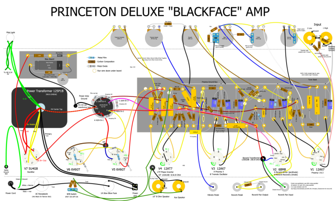
Princeton Deluxe v1.0-alt.png


This layout shows the more logical way to do it: run a wire from the turret where R49 (220k) ends to the volume pot and then – because of physical proximity – put the C13 (.001uF) coupling cap between the volume pot and the tube socket. Except in my case, I don't actually have that second turret, so I ran the 220k resistor directly from the start turret to the volume pot, without the wire. It was just long enough. Ugly but pragmatic.

This design worked well but it presented a different practical problem. A knob on the back on the amp works best as a “set and forget” thing (since you can’t see what it’s set to). And I really wanted to have a “DR default” as the standard setting, but then also options for “more gain” (turn the pot up) and “cleaner” (turn it down). I could measure the exact position that gave the required gain factor (5.3V AC peak to peak on V4A grid at 7.5 on the knob....), but marking this on the back of the chassis as the “default” position was not very useful if I couldn’t see it. At this point, I started researching detent pots and indexing knobs that would “click” into a default position at about 75% turn, but no very good options presented. (A good friend of mine is going to 3D print me one though and I can't wait to try it!)

So I decided on a different solution: a three-way rotary switch with options for “cleaner”, “normal” and “more gain” using fixed resistors. Again, it was most practical to wire these after the 220k “mixing” resistor (R49). And again I used measurements and experimentation to arrive at the values for resistors to ground: 68k gave the a gain very close to the stock Deluxe Reverb amount. I chose 33k for “cleaner” (remember: lower resistance means more signal is going to ground and so less signal is going into the phase inverter), and 220k for the “more gain” option. Here’s what that looks like in schematic and layout form:

IMG_0519.JPG


Princeton Deluxe v1.0-gain-switch.png


You’ll notice R50 is gone and replaced with the (comically large… it doesn’t seem to want to to be resized in DIY Layout Creator) three-way rotary switch that has three different resistors to ground. And again, I’m using the switch lug as a way soldering point for the mixing resistor (which in the real world runs directly to the switch without the extra wire and turret that I don’t have) and second coupling capacitor.

And with that, I decided enough was enough. On the inside it looks like this:

IMG_8961.jpeg


See if you can spot the rotary switch next to the speaker output jack!

After a few more tests and voltage measurements, I boxed it back up in the cabinet and recorded a bunch of different loops to try to demonstrate the different tones I could get out of this amp. Here is a video that shows some of those:

 
Last edited:

optilude24

TDPRI Member
Joined
Sep 19, 2023
Posts
22
Age
41
Location
UK
For anyone following along at home... Attached to this message you'll find the schematics (with and without the "more gain" switch), and DIYLC layout drawings (I can't seem to upload the .diylc files themselves on this forum, but I'm happy to share!), and the drill template.

Below are some of my voltage readings. You may notice many of them are low, which is due to the fact that I'm using a Princeton power transformer as well as the more power-hungry 6BM8 tube. In practice it seems to be fine.

I don't have a Deluxe Reverb to compare with side-by-side, but I have watched videos of people demonstrating them at various volumes and settings. To my not entirely unbiased ears, it sounds the same. :)

I highly recommend Rob Robinette' amp pages for more information about building and modifying tube amps. The safety information is particularly important. I also made a YouTube playlist of various videos (including the inimitable Uncle Doug) that I watched to learn more.

I get my kits and parts from Modulus Amplification in the UK. I can't recommend them enough. Great quality and great service.

And I owe a deep gratitude to Derek Alderman, without whose patience and wisdom and advice none of this would ever have worked.

This project was huge fun. I started in late November 2023 and finished by the end of January. I learned a lot. And I'm really happy with the results.

Voltage readings

Code:
Tung Sol tubes installed
Total bias resistance (10k + trim pot in series): 21.6k

Node A: 348V
Node B: 327V
Node C: 218V
Node D: 170V

Heaters: 5.6VAC at pilot light, 5.5VAC at V1
Rectifier heaters: 4.5VAC
PT HV: 283VAC x 2 = 566VAC

V1A Plate: 120V
V1A Cathode: 0.75V
V1B Plate: 120V
V1B Cathode: 0.77V

V2 Pentode Cathode (pin 2): 22V
V2 Pentode Grid (pin 3): 20mV
V2 Pentode Plate (pin 6): 320V
V2 Pentode Screen (pin 7): 220V

V2 Triode Cathode  (pin 8): 1.6V
V2 Triode Plate (pin 9): 133V

V3A Plate: 118V
V3A Cathode: 0.76V
V3B Plate: 201V (with tremolo switch off)
V3B Cathode: 1.6V

V4A Plate: 130V
V4A Grid: 34V
V4A Cathode: 51V
V4B Plate: 116V
V4B Grid: 37V
V4B Cathode: 51V

V5 Plate: 340V
V5 Cathode: 25.2mV
V5 Screen: 326V
V5 Grid: -24.4V

V6 Plate: 340V
V6 Cathode: 25.6mV
V6 Screen: 326V
V6 Grid: -244V
 

Attachments

  • IMG_0519.jpeg
    IMG_0519.jpeg
    229.1 KB · Views: 95
  • IMG_0525.jpeg
    IMG_0525.jpeg
    229.2 KB · Views: 112
  • Princeton Deluxe v1.0-gain-switch.png
    Princeton Deluxe v1.0-gain-switch.png
    505.3 KB · Views: 116
  • Princeton Deluxe v1.0-alt.png
    Princeton Deluxe v1.0-alt.png
    501.3 KB · Views: 93
  • Princeton Deluxe v1.0.png
    Princeton Deluxe v1.0.png
    495.8 KB · Views: 95
  • IMG_0512.jpeg
    IMG_0512.jpeg
    65.6 KB · Views: 99
Last edited:

King Fan

Doctor of Teleocity
Ad Free Member
Joined
Jan 1, 2013
Posts
12,183
Location
Salt Lake City
Amazing documentation and diagrams. Thanks.

Below are some of my voltage readings. You may notice many of them are low, which is due to the fact that I'm using a Princeton power transformer

Did you say which PT? As you'll know, PR PT clones vary a good deal in HT and current output.
 

Peegoo

Telefied
Ad Free Member
Joined
Oct 11, 2019
Posts
31,576
Location
Beast of Bourbon
WOW! That looks and sounds like a nice build. You put a whole lot of thought into why you did what you did with the changes, and it paid off.

Beautiful work!
 

optilude24

TDPRI Member
Joined
Sep 19, 2023
Posts
22
Age
41
Location
UK
WOW! That looks and sounds like a nice build. You put a whole lot of thought into why you did what you did with the changes, and it paid off.

Beautiful work!

If it looks well thought-through it was probably Derek's input, and if it's a bit hacky then it's probably all me :p
 

mountainhick

Tele-Afflicted
Joined
May 2, 2021
Posts
1,878
Location
Rocky Mountains
Thanks. Yes, TLDR, but I did click on the pics, and final schematic. Thanks especially for the 6BM8 one tube reverb circuit! I've built one each single tube reverb with 12ax7 and 12at7, Haven't optimized them yet, but I am curious about trying the 6BM8. The reverb does sound good to me too.

Nice build.
 

DerekAlderman

TDPRI Member
Joined
Jan 30, 2024
Posts
20
Age
47
Location
Washington DC
First I want to say that while the OP is pretty new to amp building, he's taken to it like a fish to water, and he's worked his butt off to get this amp sounding as amazing as it is. I've taught a few people this craft in my day, but I've never had a student work so hard on learning the ins and outs of amp building.

It's quite lucky we ended up working together on this project. Years ago when I first got into amp building I was a regular contributor to the old AX84 forum. One of the other regular posters there was Paul Fawcett, who helped edit Merlin Blencowe's books (of Valve Wizard fame). One day I began exploring the idea of reverb circuits and trying to find just a good alternative way of doing it other than the 2 main methods Fender used. Those methods being the 6G15 method and the blackface method. Fawcett taught me just about everything I know about reverb, and he showed me that the key was that reverb tanks require both high gain and high current.

At the time, for the heck of it, I had gutted my Fender Hot Rod Deville to use it for a few experimental circuits. I wanted to replace the solid state reverb with an all tube reverb. After many revisions, I ended up developing two reverb circuits, one of which I used on the Hot Rod Deville and one that got put on the shelf that I never ended up using until the OP and I began talking.

Each circuit was designed to use a single preamp tube. The circuit used in my Hot Rod Deville uses a standard Fender style tank and reverb transformer, 25k to 8 ohm. But the one I used on my Hot Rod Deville uses a single 12AT7 as the driver and the recovery. I had asked Paul Fawcett about using a 12DW7, which has a 12AU7 and 12AX7 in the same bottle, but Paul advised against it, showing me that a reverb driver needs high gain as much as it needs high current.

The result was okay. The reverb was stronger than what you'd find on a typical Marshall with their "hint of reverb" circuits. But it was not anything near the very thick and rich reverb you'd typically get from a Fender reverb.

The other circuit I thought about would use a pentode/triode tube. It may seem odd to think about this now, but quite possibly the most small tubes ever designed were pentode/triode tubes. They were used in a ton of radio and television circuits. All I had to do is find just one of those tube types where the pentode was power tube and the triode was high gain. That way, a 1 tube reverb circuit could be made using a method similar to what Fender used in the 6G15 circuit.

After spending a day going through my RC30 manual, I finally found the perfect tube for this, the 6BM8, which luckily was used in some other amp design (an Ampeg maybe?) which gives it enough demand to be one of the few pentode/triode tubes that are still being made today. The pentode side is quite perfect for this, it has a max Class A performance of 4-7 watts and the reverb transformer is limited to about 3.5 watts, so the pentode side can drive the circuit cleanly and easily. The recovery triode is very much like a 12AX7, it has a gain of 100, but I should note that it does NOT bias the same way as a 12AX7. While you can center bias a 12AX7 using a 1k5 cathode resistor, you need a higher resistor value for center bias on the triode side of a 6BM8. A 4k7 resistor will give you center bias.

For the pentode driver side, the OP and I found that 2k7 had the correct dissipation, which surprise surprise is the same value used in the double 12at7 circuit if memory serves.

From what I've heard from sound demos the OP has provided me, this circuit performs just as well as the stock blackface circuit. And because this requires just a single tube, instead of the usual 3 triodes, it frees up a triode to replace the cathodyne phase inverter for a LTP PI. This way, we can get a single channel Deluxe Reverb style performance out of a Princeton Reverb amp.

The downside is that a 6BM8 uses 780mA of heater current rather than the 300mA a 12AT7 uses, so it pushes heater draw a bit high. This typically isn't a concern as most amps are to some degree over engineered, but it will depend on what iron you use. If anyone decides to copy this circuit, it may be better to play things safe and use a DR power transformer instead of a PR transformer if you'd have no issues mounting it in a PR chassis. The OP originally was using JJ 6V6s tubes, which are 14 watts instead of the 12 watts of true 6V6s. The JJ's use 500mA of heater current per bottle while true 6V6s use 450mA. This means for a traditional PR circuit, the heater current draw is 2.1A. With a traditional PR and JJ 6V6s heater current is 2.2A. With traditional 6v6's and the 6BM8 heater current bumps up to 2.58A. Whatever transformer you opt to use, bare this in mind. A good match to heater current should run around 0.5A more than you're expected current draw, so a transformer with 3A of heater current would work for this project.
 

optilude24

TDPRI Member
Joined
Sep 19, 2023
Posts
22
Age
41
Location
UK
First I want to say that while the OP is pretty new to amp building, he's taken to it like a fish to water, and he's worked his butt off to get this amp sounding as amazing as it is. I've taught a few people this craft in my day, but I've never had a student work so hard on learning the ins and outs of amp building.
Obsession. I've been known to be soldering during video calls. :p It's a lot of fun. Crucially it's probably more fun than actually practicing guitar... And I might just need a Tweed Deluxe style amp one day?
 

mountainhick

Tele-Afflicted
Joined
May 2, 2021
Posts
1,878
Location
Rocky Mountains
First I want to say that while the OP is pretty new to amp building, he's taken to it like a fish to water, and he's worked his butt off to get this amp sounding as amazing as it is. I've taught a few people this craft in my day, but I've never had a student work so hard on learning the ins and outs of amp building.

It's quite lucky we ended up working together on this project. Years ago when I first got into amp building I was a regular contributor to the old AX84 forum. One of the other regular posters there was Paul Fawcett, who helped edit Merlin Blencowe's books (of Valve Wizard fame). One day I began exploring the idea of reverb circuits and trying to find just a good alternative way of doing it other than the 2 main methods Fender used. Those methods being the 6G15 method and the blackface method. Fawcett taught me just about everything I know about reverb, and he showed me that the key was that reverb tanks require both high gain and high current.

At the time, for the heck of it, I had gutted my Fender Hot Rod Deville to use it for a few experimental circuits. I wanted to replace the solid state reverb with an all tube reverb. After many revisions, I ended up developing two reverb circuits, one of which I used on the Hot Rod Deville and one that got put on the shelf that I never ended up using until the OP and I began talking.

Each circuit was designed to use a single preamp tube. The circuit used in my Hot Rod Deville uses a standard Fender style tank and reverb transformer, 25k to 8 ohm. But the one I used on my Hot Rod Deville uses a single 12AT7 as the driver and the recovery. I had asked Paul Fawcett about using a 12DW7, which has a 12AU7 and 12AX7 in the same bottle, but Paul advised against it, showing me that a reverb driver needs high gain as much as it needs high current.

The result was okay. The reverb was stronger than what you'd find on a typical Marshall with their "hint of reverb" circuits. But it was not anything near the very thick and rich reverb you'd typically get from a Fender reverb.

The other circuit I thought about would use a pentode/triode tube. It may seem odd to think about this now, but quite possibly the most small tubes ever designed were pentode/triode tubes. They were used in a ton of radio and television circuits. All I had to do is find just one of those tube types where the pentode was power tube and the triode was high gain. That way, a 1 tube reverb circuit could be made using a method similar to what Fender used in the 6G15 circuit.

After spending a day going through my RC30 manual, I finally found the perfect tube for this, the 6BM8, which luckily was used in some other amp design (an Ampeg maybe?) which gives it enough demand to be one of the few pentode/triode tubes that are still being made today. The pentode side is quite perfect for this, it has a max Class A performance of 4-7 watts and the reverb transformer is limited to about 3.5 watts, so the pentode side can drive the circuit cleanly and easily. The recovery triode is very much like a 12AX7, it has a gain of 100, but I should note that it does NOT bias the same way as a 12AX7. While you can center bias a 12AX7 using a 1k5 cathode resistor, you need a higher resistor value for center bias on the triode side of a 6BM8. A 4k7 resistor will give you center bias.

For the pentode driver side, the OP and I found that 2k7 had the correct dissipation, which surprise surprise is the same value used in the double 12at7 circuit if memory serves.

From what I've heard from sound demos the OP has provided me, this circuit performs just as well as the stock blackface circuit. And because this requires just a single tube, instead of the usual 3 triodes, it frees up a triode to replace the cathodyne phase inverter for a LTP PI. This way, we can get a single channel Deluxe Reverb style performance out of a Princeton Reverb amp.

The downside is that a 6BM8 uses 780mA of heater current rather than the 300mA a 12AT7 uses, so it pushes heater draw a bit high. This typically isn't a concern as most amps are to some degree over engineered, but it will depend on what iron you use. If anyone decides to copy this circuit, it may be better to play things safe and use a DR power transformer instead of a PR transformer if you'd have no issues mounting it in a PR chassis. The OP originally was using JJ 6V6s tubes, which are 14 watts instead of the 12 watts of true 6V6s. The JJ's use 500mA of heater current per bottle while true 6V6s use 450mA. This means for a traditional PR circuit, the heater current draw is 2.1A. With a traditional PR and JJ 6V6s heater current is 2.2A. With traditional 6v6's and the 6BM8 heater current bumps up to 2.58A. Whatever transformer you opt to use, bare this in mind. A good match to heater current should run around 0.5A more than you're expected current draw, so a transformer with 3A of heater current would work for this project.

Like the OP, Helluva first post to this forum, thank you! Hope you stick around!
 

Paul-T

Tele-Holic
Joined
Nov 23, 2018
Posts
850
Location
London
This is great. Thank you; especially as I've been mulling over a Princeton with LTP for a while now. Excellent information and problem-solving.
 

optilude24

TDPRI Member
Joined
Sep 19, 2023
Posts
22
Age
41
Location
UK
This is great. Thank you; especially as I've been mulling over a Princeton with LTP for a while now. Excellent information and problem-solving.

Do it. It's great. I don't know why Fender doesn't sell this type of circuit.
 

joulupukki

Tele-Afflicted
Joined
Nov 26, 2020
Posts
1,105
Location
Utah
@optilude24 Excellent build and great documentation of the journey! Thanks for sharing it with us. I'm a big fan of the 1-channel Deluxe Reverb amps. Perfect size & tone for ages. I'm using a NEO speaker in mine and that helps keep the weight down as well (The Mojotone British NEO).
 

Uncle Daddy

Friend of Leo's
Joined
Sep 26, 2015
Posts
3,653
Location
Maldon, England
Do it. It's great. I don't know why Fender doesn't sell this type of circuit.
It would probably be a bit too close to the existing Deluxe Reverb. It is supposed to be a step up from the Princeton- combining the two would likely hit sales of both.

I don't know if your PT has a 230v primary tap- I wonder if connecting that to a 240v input would give the heaters a boost?
 
Top