Champ 600 Reissue and Hammond 290ax Power Transformer?

  • Thread starter reedkm1991
  • Start date
  • This site may earn a commission from merchant affiliate links like Ebay, Amazon, and others.

reedkm1991

TDPRI Member
Joined
Dec 9, 2022
Posts
3
Age
34
Location
Ohio
I should preface this post by admitting that as a mechanical engineer, I am likely not knowledgeable enough in electronics to have undertaking this project; but alas could not resist the urge to tinker! So please forgive my shortcomings and lack of circuit understanding.

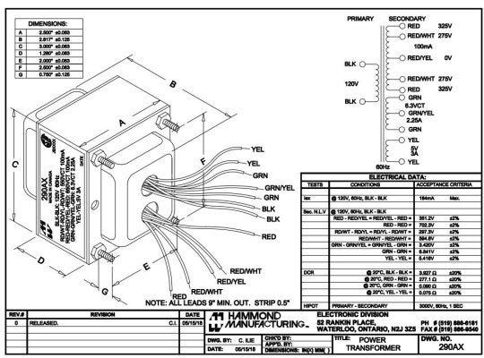
I recently replaced the output transformer on my Champ 600 reissue with a Hammond 1760cp, and it sounded so darn good I decided it would be worthwhile to also replace the Chinese power transformer with a Hammond 290ax. After reviewing the 290ax schematic, both OEM and 290ax have primaries rated at 120V and Secondary rated at 275V and 6.3V, so I assumed it would be compatible.

I installed the 290ax by attaching the black leads for the primary to J11 and J18, which is where the primary leads were attached for the OEM trans. For the secondary, I attached red/white to J13 and red/yellow to J14 to obtain 275V, then connected Green and Green to J9 and J10 to obtain 6.3V, then taped off the remaining leads.

I don't have a variac or or osctiliscope to safely bring the circuit up to power, so I plugged the amp in and flipped the switch expecting to quickly power down if something were wrong. Upon powering up, the amp immediately smoked the 1A Fuse in F1. I Checked the PCB for damage or shorts and could not find any obvious faults. Also, I could not find current ratings on the OEM trans, so is the 290ax perhaps drawing more current than the OEM, and therefore not compatible, and if so, is there a simple resistor or capacitor value I could change to make the 290ax compatible?

Thanks in advanced for any suggestions!
 

Attachments

  • 290axschematic.JPG
    290axschematic.JPG
    158.4 KB · Views: 118
  • champ600schematic.JPG
    champ600schematic.JPG
    50.2 KB · Views: 94

Jon Snell

Friend of Leo's
Joined
Aug 31, 2015
Posts
2,160
Location
Jurassic Coast, Dorset. Great Britian.
Your choice of transformer is wrong.
It is the wrong specification ... but it could work.
Check the damage has been limited and not 'cooked' the new transforme by disconnecting and insulating (temporally) the secondary leads and power up again.
If all is OK, the transformer may be OK still.
Try wiring in sections. Check the heaters first J9 & J10 (Grn Grn) if OK check the high voltage bit.
It may be a wire was not insulated ... I can't see it so look and take note.
 

tubedude

Friend of Leo's
Joined
Jul 26, 2013
Posts
3,245
Location
east georgia
Your new xfmr has a center tap. The original doesn't. The rectifier must be changed to use it. Better to find a correct replacement.
 

JPKmusicman

Tele-Meister
Joined
Nov 6, 2022
Posts
361
Location
Toneville
I re-edited my entire post. I now agree that transformer was designed for a tube rectifier, not diodes. The more I read into it there is no easy way to use a diode full bridge with the center tap transformer (See attached. None of them adapt to your schematic). There might be a way but not one I could find in a quick search. So I agree with above, get the right transformer.
 

Attachments

  • FunWithBridgeRectifiers.png
    FunWithBridgeRectifiers.png
    91.5 KB · Views: 48
Last edited:

2L man

Friend of Leo's
Joined
Nov 23, 2020
Posts
4,694
Age
65
Location
Finland
Instead of tube rectifier A-circuit work using silicon diodes. Output HV voltage comes higher because SS diodes voltage loss is much lower and "sag-effect" comes very small.

That H290AX is versatile when it has two HV outputs. 325V could be made "sagging" supply for OT feed possibly using tube rectifier. 275V can be made "stiff" for power tube Screens and pre amp. Or 325V made stiff and then power tube anodes operate higher voltage. Anyway then power tube anode current does not effect other stage voltages much and they will operate "cleaner"
 
Last edited:

reedkm1991

TDPRI Member
Joined
Dec 9, 2022
Posts
3
Age
34
Location
Ohio
Hi all, thanks for your replies and helping me understand the Champ 600's circuitry, which I should have spent more time researching before starting this project. I searched through Hammonds documentation for PTs that would be compatible with the SS diodes, however the voltage specs don't seem to match the OEM 100%. Do you think any of the following Hammond PTs would be compatible?

Dimensionally, the 290ABX and 290XX match the OEM bolt pattern.
 

Attachments

  • 269BX.JPG
    269BX.JPG
    124.3 KB · Views: 40
  • 290ABX.JPG
    290ABX.JPG
    168 KB · Views: 42
  • 290XX.JPG
    290XX.JPG
    129.6 KB · Views: 38
Last edited:

2L man

Friend of Leo's
Joined
Nov 23, 2020
Posts
4,694
Age
65
Location
Finland
I did not find any free download Champion 600 schematic and stamp size vere so fuzzy that voltages were unreadaple. Of those I would use 290XX because it is smallest but still powerful enough for 5W SE amp. Bridge Rectified and Filtered 260VAC will turn to about 365VDC. If that is not enough it is possible to connect 20VAC series with 260VAC and then HV DC output comes 390VDC.

If you don't mind "correct" look consider toroidal PT. Antekink 50VA are powerful enough for 5W SE amp and come many output voltages and pricing is reasonable. Toroids electromagnetic stray field is weaker than EI-core PT and there comes less hum which SE OT interaction with PT and possible Choke is prone. Mounting toroid flat over opening and tieing down thru holes using wax twine or any strong binding twine is OK but tie wraps are not. Also putting some rubber between chassis and toroid is always good.
 

JPKmusicman

Tele-Meister
Joined
Nov 6, 2022
Posts
361
Location
Toneville
Have you considered just leaving the Chinese PT in there? I'm not sure what you'd be gaining with the switch? The OT I can see the point, but the PT sounds like a bunch of gymnastics for no payout. Won't change the tone in my opinion.
 

2L man

Friend of Leo's
Joined
Nov 23, 2020
Posts
4,694
Age
65
Location
Finland
Here ya go.
Thanks! I think 260VAC output is better than 280VAC for 6V6 SE when operating point move to left and comes better centered to the loadline but only when amp is put running true voltages can be measured. Loadline could look like this attachment.
 

Attachments

  • Universal loadline calculator for vacuum tubes - Vacuum Tube Amplifiers - DIY(22).PDF
    91.8 KB · Views: 40

reedkm1991

TDPRI Member
Joined
Dec 9, 2022
Posts
3
Age
34
Location
Ohio
I measured my outlet voltage at 124VAC, so after the step up/down I should be at 275VAC/6.6VAC at the secondary. I think this is within range for 6v6 and 12ax7. Thank you all for your help!
 
Top