Ampeg B-15 Planning Stages

  • Thread starter BuzzKing
  • Start date
  • This site may earn a commission from merchant affiliate links like Ebay, Amazon, and others.

BuzzKing

TDPRI Member
Joined
Sep 7, 2009
Posts
73
Location
Gilroy, CA
I know this is a bass amp but I would love your guys help on this since you are all so much more knowledgeable about tube amps than I am.

I am planning to build an amp based on the Ampeg B-15. This will not be a period correct build and will not be an exact copy. I plan to incorporate elements from the vintage amps as well as the reissue and some of the "kits" that are available.

There were many variations of this amp produced from the early sixties to the early seventies. A handbuilt reissue was recently made by Ampeg in limited quantities. And I have found two currently available/published "kits" online. I have located and researched all the schematics.

For those who are interested:
Ampeg schematics: (link removed)
Trinity Trip Top schematics: click here
CtG Electronics schematics: click here

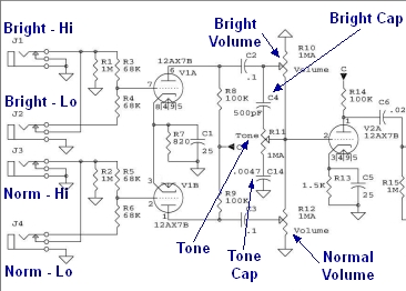
For those of you that are not familiar with the Ampeg B-15 it is a low powered tube amp with 6SL7 preamp tubes and a Baxandall tone stack. The variations are largely in the type of power tube biasing and the type of rectification. All the schematics I have looked at pretty much use the same preamp and phase inverter with the exception of the location of the volume pot (either before or after the tone controls).

I will be incorporating switchable bias (adjustable fixed vs. cathode) and switchable rectification (tube vs. SS). I will either incorporate two channels with the volume pot in the two different locations or I will try to come up with a switching scheme to "move" the volume pot.

Where I am struggling in the design phase is in three areas.
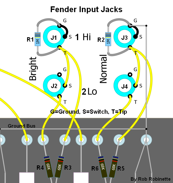
1) Input wiring / input impedance
2) Heater center tap
3) Filter caps

I will address each of these questions more specifically in separate posts.

I will publish schematics and layouts when I finish them and will ultimately start a build thread.

I would really appreciate your guys help along the way.

Thanks,
BuzzKing
 

BuzzKing

TDPRI Member
Joined
Sep 7, 2009
Posts
73
Location
Gilroy, CA
Question #1 Input wiring / impedance.

Based on all of the schematics I have looked at there are at least 6 different variations of input wiring and input impedance, even among the actual Ampeg produced amps. Seems like they changed things every few years.

image removed

I have made myself quite crazy trying to calculate the different input impedances and trying to determine the most appropriate grid stop and grid leak resistor values for my build.

I would prefer to place the grid leak resistors at the input jack and the grid stop resistors at the tube socket as shown below:

image removed

I understand in this configuration the grid stop resistor will be included in the total grid leak resistance but based on the large difference between the resistor values I expect that is a negligible effect.

So what I really need help with is deciding the best values for R1 and R2. I will be using this with passive basses in the studio and rehearsal. From the above schematics the values for the grid stop range from 47K to 330K and the total grid stop resistance ranges from ~60K to 5.6M.

I have read that larger grid leak resistance introduces noise and lower gird leak resistance can cause pickup loading. I also understand that smaller gird stop resistance doesn't filter as much noise and that the higher grid stop resistance can cut higher frequencies. So I am just not sure where to settle on those values for my build.

Thanks in advance for the help,
BK
 

clintj

Friend of Leo's
Joined
Apr 4, 2015
Posts
4,957
Location
Idaho
For your grid stopper you can calculate a starting value based on the low pass equation and the Miller capacitance of the tube in question (found on the datasheet). Since you are choosing shielded cable, there is an additional capacitance associated with the cable to consider in the equation. That value is usually listed by the manufacturer and dependent on length of cable.

Merlin usually considers 20 kHz as a starting point for the roll off frequency. High enough to allow full audio range, while blocking higher frequencies and the ability to pick up AM stations. The input stoppers are also good candidates for metal film resistors to minimize noise.
 

robrob

Poster Extraordinaire
Ad Free Member
Joined
Dec 29, 2012
Posts
8,700
Location
United States
Fender standard values are 1M and 33k for your preferred single input.

How many inputs do you plan to use? If two per channel then I recommend you use Fender's standard 4 input wiring so you get a "High" input that uses the two 68k grid stoppers in parallel for 34k of grid stop resistance and 1M of input impedance. The "Low" input cuts the input signal voltage by 50% using the two 68k grid stoppers as voltage dividers. It has 68k of grid stopper resistance and 68k of input impedance. More info here: https://robrobinette.com/How_Fender_Input_Jacks_Work.htm

Fender_Input_Jacks_0.jpg


Fender_Input_Jacks_3.png
 

andyfromdenver

Friend of Leo's
Joined
Dec 21, 2011
Posts
4,703
Location
grandpa's
+1 w robrob and I wouldn't sweat it too much. I do think a hi lo is good incase you use active or kybds.

I recommend a thiele cab like Wally recommended for me :). awesome sound.
ImageUploadedByTDPRI1449152342.220742.jpg

I am a fan of simple and reliable.
SSR and good filtering for clean tight bottom
 

bparnell57

Poster Extraordinaire
Joined
Feb 10, 2014
Posts
6,100
Location
Hanover, PA
Great to see someone else looking to build a vintage style tube amp.

Are you doing this to save money or to gain experience?

I see lesser examples of original B15 and B18 amps going for $900 sometimes around here.
 

BuzzKing

TDPRI Member
Joined
Sep 7, 2009
Posts
73
Location
Gilroy, CA
Thanks for the input so far. I would like to play around with calculating the grid stop value. Can you point me to an equation I can use?

I am very familiar with the Fender input scheme having just finished the Tweed Proluxe. I was just unsure if there would be any diffenerences required given that its a bass amp and uses 6SL7's instead of 12A?7's in the preamp. Also, as shown in the original post there are many variations of inputs schemes used on the B-15 amps none of which are the same as the Fender.

I have a friend Jonathan Reiner who builds botique bass preamps and amps. He has a cool Youtube channel and Facebook page for those interested in bass amps/cabs. I bought a 6SL7 based rackmount preamp from him last year that is currently what I gig with. I shot this question out to him as well. This was his reply:

"I'd go with 1 - 2.2M on the input, I like the 2.2M as I can hear just a hint more sparkle though it's subtle. The grid stop resistors are there to keep out RF and prevent blocking distortion in the later stages. They created a high frequency roll-off by combining with the Miller capacitance of the tube. IIRC, the 6SL7's Miller cap is slightly higher than a 12ax7 - 47K shouldn't make much of an audible difference in the top end and is a good choice for the first stage. A 330K will roll off everything down into the midrange - it's a common value in high gain designs, but it might be too much for a somewhat clean bass amp. For the second, third, etc. stages, I'd go with something in the 10-20K range to start. You can go higher if you want to tame the top end - it's a great tool for voicing an amp that a lot of folks overlook. Make sure you attach them directly to the pin of the tube socket."

As far as why I am doing this - certainly not to save money! I am doing this to learn and just for the shear fun of it. Also, generally speaking when it comes to basses, guitars, effects or amps I generally want something you can't just buy off the shelf. As with this project I will be incorporating elements from many iterations of this amp. The only thing commercially available that's close to what I want to build is the Ampeg Heritage B-15. They only made 50. The original price tag was ~$4K and I am not even sure if there are any more available. So I guess I am gonna save some money!

More questions to follow.

Thanks,
BK
 

jhundt

Doctor of Teleocity
Joined
Mar 23, 2003
Posts
13,189
Age
71
Location
Netherlands
well I for one am looking forward to following your build. I love those old flip-tops, used to use one for recording (with an old Gretsch guitar).

I can't really offer any wisdom or advice re: input wiring. I guess I would just look at the old 60's Ampeg design, since I like old 60's Ampegs.
 

ThermionicScott

Poster Extraordinaire
Joined
Dec 3, 2005
Posts
6,501
Age
44
Location
CID
Very cool idea for a build! And it's great that so many of the original schematics are available -- it's fascinating to watch how they evolved.
 
Last edited:

BuzzKing

TDPRI Member
Joined
Sep 7, 2009
Posts
73
Location
Gilroy, CA
I was cleaning up my office in preparation for repainting the walls. To my surprise I found a book I had bought several years ago and forgot that I even had: Merlin Blencowe's "Designing Tube Preamps for Guitar and Bass." Well I have spent the last several evenings doing some reading. The more I read the more I understand and the more confused I get all at the same time!

Anyway in the book I found the calculations for the grid stop value.

Cin = CgK + Cga(1 + A)

Rg = 1 / 2 pi f C)

I have been able to locate all the values except for A which is the voltage gain in the tube. I assume this number is quite dependent on the actual circuit the tube is placed in as well as the B+ voltage.

I have found some sources on the interwebs that suggest the Vg for the 6SL7 is anywhere form ~28-45 volts. I also found some references to other calculations and using the actual circuit from my current design these calculations suggest the Vg in my circuit is 28.5 volts. I am just not completely confident I understand these calculations enough to know that's the right value.

However, using those numbers in the above calculations I come up with a grid stop value that ranges from 30.6 - 47.7K depending on what voltage I use. So it seems that using a grid stop resistor of either 33K or 47K would be appropriate.

Do these voltage gains for the 6SL7 seem to be in the right ballpark or am I way off?
 

BuzzKing

TDPRI Member
Joined
Sep 7, 2009
Posts
73
Location
Gilroy, CA
Here is the current design for the preamp section:

image removed

The dashed lines indicate shielded cable. There are sub boards used for the tone controls so I plan on using shielded cable for those connections that cross the chassis. A goes to the filter caps. B goes to the PI tube input.

There are a few options I am still considering:
1) Bright cap on both channels + making bright caps switchable
2) May not keep the linked input. I am not sure this amp calls for it. This is a design feature in the Trinity Trip Top kit. I have it in there for now but may remove it.
3) May change values of channel isolation resistors and B+ voltage drop resistors. These also varied quite a bit among the schematics I am using as reference.
4) I am still considering working on using a single channel and using a switching scheme to "move" the position of the volume pot as the preamps are essentially the same otherwise. This is pretty complicated with 6 switching points and would require a 6PDT switch or 6 pole/2 selection rotary switch. Still playing around with it.

If anyone sees anything glaringly wrong please chime in.


BK
 

ThermionicScott

Poster Extraordinaire
Joined
Dec 3, 2005
Posts
6,501
Age
44
Location
CID
I was cleaning up my office in preparation for repainting the walls. To my surprise I found a book I had bought several years ago and forgot that I even had: Merlin Blencowe's "Designing Tube Preamps for Guitar and Bass." Well I have spent the last several evenings doing some reading. The more I read the more I understand and the more confused I get all at the same time!

Anyway in the book I found the calculations for the grid stop value.

Cin = CgK + Cga(1 + A)

Rg = 1 / 2 pi f C)

I have been able to locate all the values except for A which is the voltage gain in the tube. I assume this number is quite dependent on the actual circuit the tube is placed in as well as the B+ voltage.

I have found some sources on the interwebs that suggest the Vg for the 6SL7 is anywhere form ~28-45 volts. I also found some references to other calculations and using the actual circuit from my current design these calculations suggest the Vg in my circuit is 28.5 volts. I am just not completely confident I understand these calculations enough to know that's the right value.

However, using those numbers in the above calculations I come up with a grid stop value that ranges from 30.6 - 47.7K depending on what voltage I use. So it seems that using a grid stop resistor of either 33K or 47K would be appropriate.

Do these voltage gains for the 6SL7 seem to be in the right ballpark or am I way off?

The voltage gain depends somewhat on the supply voltage, too (but isn't expressed in "volts". ;)) I'm usually too lazy to calculate it, so I generally go to the back of the RCA manual and see if I can find an example setup that's close enough.

In the 1954 RCA manual (RC-17) that I have on my desk here, that's page 261. So for a supply voltage of 300V, 470k plate resistor, 6.3k cathode resistor (close enough) and a 1-meg grid resistor at the following stage (it's important!), you'd be looking at a voltage gain of about 50 if the input stage had a cathode bypass cap.

It'll be a little less without a bypass cap, though. Let me see if I can find a conversion factor for that. EDIT: check out pages 24 and 36, formula IV, in Merlin's book, to figure out A. Looks like gain gets cut by about 1/3 in his example. EDIT2: Assuming a plate resistance of 44k for the 6SL7 (which will vary depending on the actual operating conditions, but is a small part of the calculation), I get a VG of about 34, which is in the same ballpark of 2/3.

Also: Merlin's books are fantastic. I learn something new everytime I pick them up. Do you have a copy of Richard Kuehnel's exhaustive analysis of the 5F6A Bassman? It's so worth it.

Sorry about all the edits. It's been a while since I've dinked around with this stuff. :)
 
Last edited:

ThermionicScott

Poster Extraordinaire
Joined
Dec 3, 2005
Posts
6,501
Age
44
Location
CID
All that said, it may be just as easy to build the amp and try your 33k and 47k resistors, using the 33k if the 47k cuts any audible high-end. The value is not super-critical -- the goal is just to block any RF interference. :lol:
 

BuzzKing

TDPRI Member
Joined
Sep 7, 2009
Posts
73
Location
Gilroy, CA
All that said, it may be just as easy to build the amp and try your 33k and 47k resistors, using the 33k if the 47k cuts any audible high-end. The value is not super-critical -- the goal is just to block any RF interference. :lol:

Scott, thanks for all the info in both your posts.

So with a Vg of 34V the grid stop value calculates as ~40K. I am not factoring the capacitance in the guitar or the shielded cable which will both add a little to Cin. So I think starting with 47K sounds pretty good.

I agree I will just change the value if I don't like the results since its pretty easy to do. I just enjoy the learning aspect of going through the calculations and research. I am pretty new to this amp building thing so I am trying to understand what I do and why I do what I do instead of just doing it.

BK
 

BuzzKing

TDPRI Member
Joined
Sep 7, 2009
Posts
73
Location
Gilroy, CA
Question #2 Heater Center Tap

Most everything I read on the interwebs suggest that 6SL7 are quieter with heater elevation instead of simply grounding the CT. How this is accomplished in the various schematics I am using varies.

There were three primary ways Ampeg accomplished this in the B-15:
1) The CT or an artificial CT was referenced to the cathode of the power tubes with or without an anti hum potentiometer (humdinger).
2) A humdinger, potential divider and an anti-ripple capacitor were referenced to B+.
3) A humdinger was referenced to the bias negative voltage.

According the Merlin Blencowe's book all are viable applications. My question is basically which is the best approach. To me using the PT CT and referencing this to the power tube cathode would be the simplest as it does not require any additional components. #2 is the most complex and uses the most components and board real estate. Adding an anti-hum pot would be pretty simple assuming I have real estate available at the rear of the chassis.

Once again just trying to learn instead of just do. Any insights are appreciated.

BK
 

ThermionicScott

Poster Extraordinaire
Joined
Dec 3, 2005
Posts
6,501
Age
44
Location
CID
I agree I will just change the value if I don't like the results since its pretty easy to do. I just enjoy the learning aspect of going through the calculations and research. I am pretty new to this amp building thing so I am trying to understand what I do and why I do what I do instead of just doing it.

BK

Totally with you there! I love learning about how these things work, and it's very rewarding to break amp circuits down and go through all of the calculations. :) People who just solder kits together using a layout without bothering to understand what each part is doing really miss out IMO.

A few years ago, I prototyped a small amp using two 6AU6 small-signal pentodes as output tubes. Since I wasn't aware of many other amps doing that, at least with a push-pull output stage, it was a really fun exercise. I threw a tube rectifier into the design just for the hell of it.

As for the heater thing, those couple of schematics showing the humdinger connected to the negative bias supply are really interesting -- I would expect that you'd get the opposite result (more hum conducted into the heaters) from what you'd want. Might be worth a try, though, for experimentation's sake! If I were building this from scratch, I'd probably just reference the humdinger to the top of the power tubes' cathode resistor (so that it will just connect to ground when in fixed-bias mode) and call it a day. If you just avoid the major sins, it's not hard to get a practically hum-free amp in the end.

- Scott
 

BuzzKing

TDPRI Member
Joined
Sep 7, 2009
Posts
73
Location
Gilroy, CA
So I thought I would post an update of my progress. Here are revision 1.3 schematics and layout:

image removed

image removed

image removed

image removed

I am already considering some changes so Rev 1.4 may be available soon. I am planning a PI grid stop and plate cap and will probably put a bright switch on the 1964 channel as well. Other than that and tweaks to the layout I should be done with the design phase. I am also working on the chassis "blueprints" and the faceplate but those aren't ready to reveal yet.

BK
 

BuzzKing

TDPRI Member
Joined
Sep 7, 2009
Posts
73
Location
Gilroy, CA
I noticed on the vintage Fender Bassman amps that the SS rectifier and bias circuitry was always placed on a separate board. Was this due to chassis real estate or is there an electronic reason to separate these components from the main board?

BK
 

BuzzKing

TDPRI Member
Joined
Sep 7, 2009
Posts
73
Location
Gilroy, CA
Well I have started sourcing parts and the lack of availability of some of the items is leading to revision 1.4 being in the works.

I was planning a 40uF/600V cap for the reservoir cap and first filter cap but I can't find anything >500V rating. So I will be using two 80uF/450V caps in series. I have calculated the required bleeder resistors as 620K based on the valvewizard recommendation. Question is what should the power rating of these resistors be? Is 2W enough?

Also, if anyone has any insights as to the question in my most previous post regarding separating the rectifier and bias circuit from the main board that would be great.

Thanks,
BK
 

ThermionicScott

Poster Extraordinaire
Joined
Dec 3, 2005
Posts
6,501
Age
44
Location
CID
Well I have started sourcing parts and the lack of availability of some of the items is leading to revision 1.4 being in the works.

I was planning a 40uF/600V cap for the reservoir cap and first filter cap but I can't find anything >500V rating. So I will be using two 80uF/450V caps in series. I have calculated the required bleeder resistors as 620K based on the valvewizard recommendation. Question is what should the power rating of these resistors be? Is 2W enough?

Also, if anyone has any insights as to the question in my most previous post regarding separating the rectifier and bias circuit from the main board that would be great.

Thanks,
BK

If you have the room for it, you could put two 20uF/600V Sprague Atoms in parallel. Those are big suckers, though. :lol:

For the bleeders/voltage-sharing resistors, I hadn't noticed Merlin's formula before. I think Fender and others just used 220k or 470k and called it a day. Since they're such high-value, they don't dissipate a lot of power. If your B+ is 470V, for example, and you used 470k resistors, each one is dropping about 235V, so it's drawing 0.5mA. Multiply that back by the voltage dropped, and you get 0.12W -- even 1/2-watt would be overkill. Doing the same math on your 620k resistors means they're even less critical. :cool:

As for why the SS rectifier/bias circuitry is on a separate board, I was hoping more learned people would chime in. But I've always figured it came down to assembly ease, or preventing switching noise from conducting into the signal path via the eyelet board. (Eyelet boards are always a little bit conductive, after all.)
 
Top