Adding a bias trim pot to a 4-terminal bias balance pot

  • Thread starter Michael Smith
  • Start date
  • This site may earn a commission from merchant affiliate links like Ebay, Amazon, and others.

Michael Smith

Tele-Afflicted
Joined
Mar 3, 2023
Posts
1,928
Location
SE Texas
This is for my "new" 1980 Vibrolux Reverb amp, but I thought I'd start a new thread for this technical question, since my main thread is mostly just photos showing the progress of the work. On the other 2 Fender amps that I have added bias adjustment trim pots to the bias balance pot (1968 Bassman and 1969 Bandmaster Reverb), the bias balance pots only had 3 terminals and the bias adjustment pot's wiper was connected to the leg of the balance pot grounded to the pot via a resistor. In this case, the wiper of the balance pot is grounded to the pot thru a resistor and each outer lug go off to the grids of the power tubes. Would I connect the wiper of the trim pot in between the resistor that currently grounds the wiper of the balance pot to ground? And connect one of the other legs of the trim pot to the bias balance pot like I did with the other 2 amps? In other words, would I just connect the bias trim pot in the same way as I did with the other 2 amps?

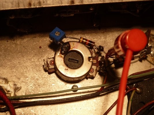
Here is a photo of the bias balance pot before any alterations. I have rebuilt the bias circuit preceding the balance pot. The sketchy connection of the resistor to the pot is factory not my work.

Edit: I looked at Rob's site, but didn't see this exact configuration.
P1050894.JPG
 
Last edited:

2L man

Friend of Leo's
Joined
Nov 23, 2020
Posts
4,586
Age
65
Location
Finland
My profession was electronics 42 years and I have learn to follow the schematic when I want circuit to function!

I have used both of these but true balance circuit on right is bit easier to set balance! They are safe circuits when pot wiper is in positive leg and if it fails bias voltage come more negative. I always use two RC filter stage bias supply so that voltage come more stable and smoother. Resistor values often must be changed and 6.8k "tail resistor" on left circuit is initially way too small.


Dual Bias and Bias Balance.gif_thumb.png
 
Last edited:

Bendyha

Friend of Leo's
Silver Supporter
Joined
Mar 26, 2014
Posts
4,382
Location
Low Saxon
Would I connect the wiper of the trim pot in between the resistor that currently grounds the wiper of the balance pot to ground? And connect one of the other legs of the trim pot to the bias balance pot like I did with the other 2 amps? In other words, would I just connect the bias trim pot in the same way as I did with the other 2 amps?
It would be helpful if you would post here how you did it on the other two amps, rather than having me to have to search for it.
Here the vibrolux as is bias schem.
viblux.JPG
 

Michael Smith

Tele-Afflicted
Joined
Mar 3, 2023
Posts
1,928
Location
SE Texas
It would be helpful if you would post here how you did it on the other two amps, rather than having me to have to search for it.
Here the vibrolux as is bias schem.
View attachment 1215724
Here is a photo of how I added the bias adjustment trim pot to the existing bias balance pot on my Bandmaster Reverb. The wiper of the blue trim pot is connected to the 10K resistor, which is coming off of one of the outer legs of the balance pot. One of the outer legs of the trim pot is soldered to the balance pot, and the other outer leg of the trim pot is not connected to anything.

P1050698.JPG

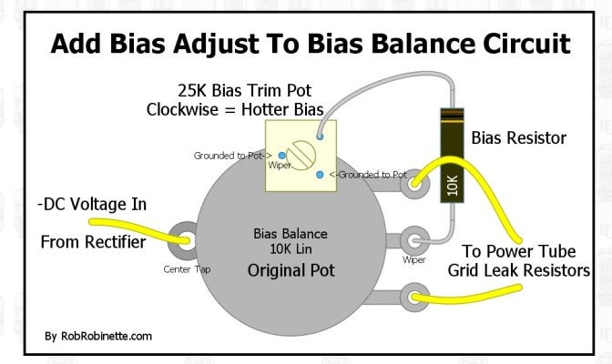
I found this diagram on Rob R's website and I think it matches up with my Vibrolux Reverb wiring. It looks like he is grounding both the wiper and one of the outer legs of the trim pot to the original balance pot, and connecting a 10K resistor from the wiper of the original pot to the other leg of the trim pot.

RobRob trim pot.jpg
 

Bendyha

Friend of Leo's
Silver Supporter
Joined
Mar 26, 2014
Posts
4,382
Location
Low Saxon
Robs method looks like a quick and simple mod that should work just fine, but I do appreciate the more elegant solutions that 2L man shows us in post #2.

Robs diagram states "-DC voltage in from rectifier", but I presume he means you to connect the middle tap to the opposing end of the 3k3 resistor that the rectifier is connected to.
Whether one connects the wiper of the trim-pot to the bias-resistor, or to the ground of the balance-pot case makes little to no difference, but it probably makes for a more stable construction if done as shown.
 

Michael Smith

Tele-Afflicted
Joined
Mar 3, 2023
Posts
1,928
Location
SE Texas
Robs method looks like a quick and simple mod that should work just fine, but I do appreciate the more elegant solutions that 2L man shows us in post #2.

Robs diagram states "-DC voltage in from rectifier", but I presume he means you to connect the middle tap to the opposing end of the 3k3 resistor that the rectifier is connected to.
Whether one connects the wiper of the trim-pot to the bias-resistor, or to the ground of the balance-pot case makes little to no difference, but it probably makes for a more stable construction if done as shown.
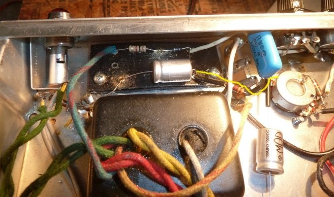
I think Rob means the negative DC voltage from the bias board is connected to the rear terminal on the balance pot. I have drawn a yellow line showing the connection to from the bias board, thru a 3.3K resistor to the rear terminal.

The terminal strip with the blue cap has nothing to do with the bias supply.

I haven't yet cleaned the flux from the bias board, so it looks pretty awful in this photo.
P1050896.JPG
 

Bendyha

Friend of Leo's
Silver Supporter
Joined
Mar 26, 2014
Posts
4,382
Location
Low Saxon
I think Rob means the negative DC voltage from the bias board is connected to the rear terminal on the balance pot. I have drawn a yellow line showing the connection to from the bias board, thru a 3.3K resistor to the rear terminal.
Basically, leave that connection as it is now.
 

Michael Smith

Tele-Afflicted
Joined
Mar 3, 2023
Posts
1,928
Location
SE Texas
Basically, leave that connection as it is now.
Yes, will do. I have completed recapping the entire amp. I have the 10K trim pot for the adjustable bias, but don't have a 10K resistor on hand to replace the 15K currently on the bias adjustment pot. I'm currently biased at 14.6 and 14.43 Watts using Sovtek 5881 WXT power tubes, which is around 58%, so the bias trim pot will have to wait until I get to my local parts store.
 
Top