Active Tone control design

  • Thread starter Jewellworks
  • Start date
  • This site may earn a commission from merchant affiliate links like Ebay, Amazon, and others.

Jewellworks

Tele-Holic
Joined
Mar 2, 2020
Posts
952
Location
Orlando
a while back, i created and built what i call my RicknDevil. 2, ECL86 tubes (triode/pentode) based on a Rickenbacker amp from 1938. very simple circuit, -input goes directly to the phase inverter which feeds the pentodes in P/P. overall, its a success, and ive been playing through it almost exclusively lately.
BUT..
it sounds and "feels" almost identical to another amp i made i call my Cyclops. 1, ECL86. triode feeds the pentode, -done. and ive been asking myself, WHY do i have 2 nearly identical amps? what can i do to make the RicknDevil a little more interesting, yet still use almost everything? and not reinvent the wheel along the way?
so i got to thinking about ACTIVE tone controls, and i looked up a few circuits. -how they're done, and (just as important) how they work.
almost all of them were using a cathode follower, which wouldnt work for me because id be loosing a gain stage. but i did come across 1 design that came off the plate. so i adopted that, and decided to go with a parallel SE output stage for my pentodes. see below...
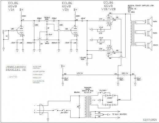
Image1.jpg

what surprised me about this is, its not that much more complex than a regular passive tone stack, but you get so much more out of it. why isnt it used more? especially in the designs i see on this forum?
i can use practically everything in my original circuit (chassis, sockets, PT, jacks)... the only thing ill need to change is my OT, which is $42. -and components to reflect the new circuit. ill probably make a custom turret board. i bought everything to make one months ago.

i would be very interested in thoughts and opinions on this design, and on Active Tone Stacks in general. pros and cons

and as a side note, i was also getting a little bit of hum, and although its minimal, i thought id up the filter cap values to see if i can knock it back. i read Merlin's article on power filtering and i didnt realize that you can use much larger value caps when using a solid state rectifier. i plan on upping the caps in the Cyclops as well.
 

2L man

Friend of Leo's
Joined
Nov 23, 2020
Posts
4,694
Age
65
Location
Finland
Interesting but what does it make different than other EQs which are Anode driven?

On low settings our Master Volume will restrain V2A output and obviously distort as well. Usually volume potentiometers are used as voltage divider.

To me it looks that solid state rectifier diodes should be ultra fast for exampe UF4007 and their higher price is well spent money. I read this in HiFi forum.

I have test multiple but smaller PS filter capacitors on RC filtering and installed series resistors also to common/return (ground) path between them to have RCR filters, all the way until B+1 output. I read this from Merlin pages and amps hum less than traditional one capacitor to B+1 PS hum and also less than Choke PS hum so its cost ratio is very good.
 

Bendyha

Friend of Leo's
Silver Supporter
Joined
Mar 26, 2014
Posts
4,423
Location
Low Saxon
Jewellworks, I like the idea of using a Baxandall style negative feedback, active tone control in a guitar amp, but have never tried it myself yet.
Here a copy of the original......
1642082538644.png


...yours is a bit of a variation on it, nice to see......BUT..... I can’t help but notice that the way you have drawn it up, puts high D.C. voltage onto the both sides of the bass pot(yellow marker being all D.C. voltage track) which makes it not only liable to give you bad scratchy noises, but I would find it a bit dangerous for my liking (an insulated plastic stemmed and bodied pot might help), but why leave out the blocking caps like Baxandall used, as I have marked in red?
1642083294073.png

Also, on the theme of hum, did you put the filament voltage on the two output tubes in reverse polarity to each other ? This can help to counter some hum in parallel output tubes. And, as mentioned in the post above, a choke filter is not a bad idea in an amp of this design, if not, then splitting your first power supply dropping resistor, the 2k2 1W, into two, 1k2 & 1k with an added filter cap, could also help.

Sorry to hack at your design, but I am just mentioning things I notice..
Your triode of the 6GW8 (on the schematic right) has a grid to cathode circuit resistance of 3M31k5 ohms; the data sheet only gives us a max. circuit value for fixed bias, and that is 1M.
1642084829809.png


...but if we look at another similar triode, like here the 12AU7, we see that the self-bias tends to be more lenient on the circuit specifications, so you might be alright.
1642084721476.png
 
Last edited:

Jewellworks

Tele-Holic
Joined
Mar 2, 2020
Posts
952
Location
Orlando
I like the idea of using a Baxandall style negative feedback, active tone control in a guitar amp, but have never tried it myself yet.
oh good! another circuit! ill add it to my list of things to try thanks!

BUT..... I can’t help but notice that the way you have drawn it up, puts high D.C. voltage onto the both sides of the bass pot

YIKES! cant have that. ill add blocking caps. this is why i post these things... thank you sir.
although i need to mention, i copied this circuit exactly from a Google search on Active Tone controls. i just double checked, and thats how its drawn. the circuit i found is using a 12AX7 tho, so that may make a difference. ... whatever. ill add the coupling caps!

Also, on the theme of hum, did you put the filament voltage on the two output tubes in reverse polarity to each other ? This can help to counter some hum in parallel output tubes. And, as mentioned in the post above, a choke filter is not a bad idea in an amp of this design, if not, then splitting your first power supply dropping resistor, the 2k2 1W, into two, 1k2 & 1k with an added filter cap, could also help.

i cant remember if i did opposite polarity on the filaments, but with this new design, i considered a choke, and i might still. i thought id bump up the filter caps first and see/hear what happens. my original has 22, 10 and 10 with the same resistor values shown here. i was getting cutoff frequencies around 15hz, 7hz... and after i read Merlins article, and saw i can go a lot bigger when using a bridge rectifier, so i bumped these all up. most of my cutoff freq's are around 1.5hz or less. if that does it, then yay. if not, ill try the dropping resistor split thing. if still not enough, ill get a choke.

Your triode of the 6GW8 (on the schematic right) has a grid to cathode circuit resistance of 3M31k5 ohms; the data sheet only gives us a max. circuit value for fixed bias, and that is 1M. / ...but if we look at another similar triode, like the 12AU7, we see that the self-bias tends to be more lenient on the circuit specifications, so you might be alright.

mmmmmm.... didnt see that either, but i do now. your Baxandall circuit might be better because its only slightly over 500k. this shows a Pentode, but im sure it can be used w/a Triode... -right?
however... that treble pot looks strange... its got 4 lugs? one going straight to ground? or is that the shell?

Sorry to hack at your design, but I am just mentioning things I notice..

no apologies needed! this is EXACTLY why i posted this! to see what i missed. im very grateful for your insights and suggestions. all good! thank you so much!
 
Last edited:

Jewellworks

Tele-Holic
Joined
Mar 2, 2020
Posts
952
Location
Orlando
actually... im not seeing HOW the Baxandall circuit works... and whats with that 4th lug to ground? without it, theres no grid reference to ground at all.
 

jjlemon

TDPRI Member
Joined
May 11, 2014
Posts
96
Location
Abertawe
I tried a bax/james active circuit in a JFET design I worked on a few years ago. It wasn't that successful, for various reasons which might not apply with tube circuits.

I tried a voltage-shunt feedback arrangement (which I understand the active stack arrangement is a form of) on my VHT s6u to replace the cathode follower. Although the input impedance is reduced and so loads the preceding stage and lowering it's gain, the lower output impedance looked to be a useful property to take advantage of, ie driving an fx loop. However, in that position, 3rd stage, it got overdriven and the distortion characteristic wasn't that good. Broken feedback loop being the reason, apparently.

If it's a clean pre amp or for HI-fi, the active bax might work really well, giving good tone response. Not sure how well it would work if the active stage is overdriven, which in this circuit it might not do due to the loading effect on the first stage. An interesting experiment to be sure.

Good luck.
 

Bendyha

Friend of Leo's
Silver Supporter
Joined
Mar 26, 2014
Posts
4,423
Location
Low Saxon
actually... im not seeing HOW the Baxandall circuit works... and whats with that 4th lug to ground? without it, theres no grid reference to ground at all.
The pot is a bit unusualy nowadays, they are available; tapped potentiometer, or you can adapt and make your own _ I've done that, and actually have a post somewhere here showing how - I'll see if I can remember where.
As to grid-ground reference, it goes in the loop like shown, the two sides being parallel, it works out at about 1M or less , depending on how the bass wiper is set.
bax.PNG

As to how it works... there has been decades of people writing about it, the concept of virtual signal earths was new back in 1952, clever man Baxandall.
Here is another amp with triode baxandall. Treble pot is centre tapped, but on the schematic looks like offset.
midget.PNG

midg list.PNG
Don't let the screened cable grounding on the schematic confuse you.
midget2.PNG
 
Last edited:

Bendyha

Friend of Leo's
Silver Supporter
Joined
Mar 26, 2014
Posts
4,423
Location
Low Saxon
You might have seen this over at https://www.angelfire.com/electronic/funwithtubes/Amp-Tone.html, if not, here is the part that might interest you. No tapped poti needed.
angel1.PNG

"As you can see the values have been scaled up to vacuum tube levels. This makes it possible for one tube to be used. The gain of the triode stage is about 50 which is a little on the low side. A pentode would be better here, but it may introduce more distortion.
I actually did connect this circuit to an amplifier and listen to it. I was quite impressed with the sound. I may well use it in a new incarnation of my original tube preamp."
 

Jewellworks

Tele-Holic
Joined
Mar 2, 2020
Posts
952
Location
Orlando
@Bendyha - i think i have seen this one. but forgot about it. but again, where are the coupling caps? i see the .047 on the output, but what about the input? shouldnt there be one before the 470k to ground?
and the values are quite different from the Baxandall
...also, just discovered THIS:
although, im not getting that Op Amp in the middle... is this the same circuit?
 
Last edited:

jjlemon

TDPRI Member
Joined
May 11, 2014
Posts
96
Location
Abertawe
You might have already seen this, the Aiken site has a white paper on designing single stage inverting feedback amps, and there's a little section about coupling caps and variations, ie whether the feedback is taken after the coupling cap to the next stage or a separate coupling cap is used in the loop. The calculations are slightly different in each case.

http://aikenamps.com/index.php/designing-single-stage-inverting-feedback-amplifiers
 

Bendyha

Friend of Leo's
Silver Supporter
Joined
Mar 26, 2014
Posts
4,423
Location
Low Saxon
@Bendyha - i think i have seen this one. but forgot about it. but again, where are the coupling caps? i see the .047 on the output, but what about the input? shouldnt there be one before the 470k to ground?
and the values are quite different from the Baxandall
...also, just discovered THIS:
although, im not getting that Op Amp in the middle... is this the same circuit?
They don't show the input cap, I guess they take it for granted that you know it's there.
TSC in the web is a great resource.
Yes, it is the same circuit, but they have it relating to I.C.'s instead of tubes - so all low impedance values. (If you look at the anglefire page they show the relationship between the two)
TSC has four versions - with single or double bass caps (fair enough), and then active or passive....?...and if you look at the James- it's the same......but that is the difference between a James and a Baxandall, the James is passive, and the Baxandall, which came out a few years later, is active.
 

SerpentRuss

Tele-Holic
Ad Free Member
Joined
Feb 17, 2021
Posts
844
Age
62
Location
North Carolina
a while back, i created and built what i call my RicknDevil. 2, ECL86 tubes (triode/pentode) based on a Rickenbacker amp from 1938. very simple circuit, -input goes directly to the phase inverter which feeds the pentodes in P/P. overall, its a success, and ive been playing through it almost exclusively lately.
BUT..
it sounds and "feels" almost identical to another amp i made i call my Cyclops. 1, ECL86. triode feeds the pentode, -done. and ive been asking myself, WHY do i have 2 nearly identical amps? what can i do to make the RicknDevil a little more interesting, yet still use almost everything? and not reinvent the wheel along the way?
so i got to thinking about ACTIVE tone controls, and i looked up a few circuits. -how they're done, and (just as important) how they work.
almost all of them were using a cathode follower, which wouldnt work for me because id be loosing a gain stage. but i did come across 1 design that came off the plate. so i adopted that, and decided to go with a parallel SE output stage for my pentodes. see below...

View attachment 939609

what surprised me about this is, its not that much more complex than a regular passive tone stack, but you get so much more out of it. why isnt it used more? especially in the designs i see on this forum?
i can use practically everything in my original circuit (chassis, sockets, PT, jacks)... the only thing ill need to change is my OT, which is $42. -and components to reflect the new circuit. ill probably make a custom turret board. i bought everything to make one months ago.

i would be very interested in thoughts and opinions on this design, and on Active Tone Stacks in general. pros and cons

and as a side note, i was also getting a little bit of hum, and although its minimal, i thought id up the filter cap values to see if i can knock it back. i read Merlin's article on power filtering and i didnt realize that you can use much larger value caps when using a solid state rectifier. i plan on upping the caps in the Cyclops as well.
This is very interesting, but could you also show or reference the thread having a schematic of your first design, with Push-Pull. I have a box of 6F12P tubes and both architectures might be fun to try.
 

NTC

Friend of Leo's
Joined
Mar 17, 2003
Posts
2,399
Don't some of the Ampeg amps use this type of circuit? See also a 5D8 Fender twin.
 

Bendyha

Friend of Leo's
Silver Supporter
Joined
Mar 26, 2014
Posts
4,423
Location
Low Saxon
Don't some of the Ampeg amps use this type of circuit? See also a 5D8 Fender twin.
I know Ampeg refers to some of their amps as having Baxandall tone stacks, but the only ones I recall seeing that looked similar, like on the GVT5 or the VT-52, were of the James, passive, type. The 5D8 has an unusual stack, but it too is not active.
 

Jewellworks

Tele-Holic
Joined
Mar 2, 2020
Posts
952
Location
Orlando
They don't show the input cap, I guess they take it for granted that you know it's there.
TSC in the web is a great resource.
Yes, it is the same circuit, but they have it relating to I.C.'s instead of tubes - so all low impedance values. (If you look at the anglefire page they show the relationship between the two)
TSC has four versions - with single or double bass caps (fair enough), and then active or passive....?...and if you look at the James- it's the same......but that is the difference between a James and a Baxandall, the James is passive, and the Baxandall, which came out a few years later, is active.

the James and Baxandall are "almost" identical. the Bandaxall has resistors on both sides of the Bass pot, AND the Treble pot. the James circuit has Caps on both sides of the Treble pot. along with a few other small changes, not to mention radically different component values.
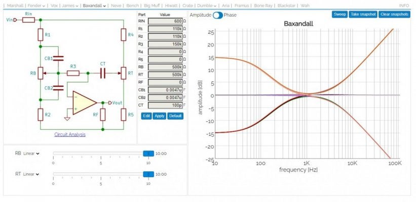
that said, i started looking at the drawing you posted against the Baxandall, (dual bass caps) and its "almost" identical as well (aside from the extra resistors on the treble pot side). so i entered "0" for the resistor values on either side of the treble pot, and adjusted all the other values to match the Baxandal you posted, and did a sweep:

below is a full frequency look at the sweep:

B-orig-full.jpg

looks good, except guitars dont go to nearly 100KHZ
so i trimmed the view to show only 30hz to 6kHZ

B-orig-30-6k.jpg

hmm... lots of low boost, but only about 5db at 6k.

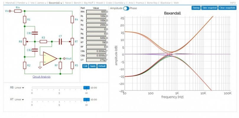
so i adjusted the values and shifted the center freq's a bit lower to get equal amounts of treble and bass boost.
I came up with this:

B-me-full-lo imp.jpg

same sweep, but 30hz to 6kHz

B- me- 30-6k.jpg

looks good. i get an equal 15db of boost on both bass and treble.

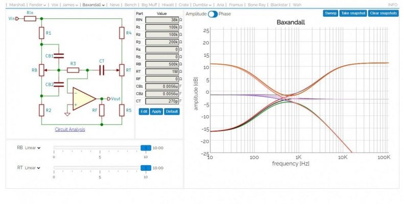
however, this is all with a low impedance input. ill be feeding this with high impedance. so i entered 38K as the input and it looks like this:

B-me-full-hi imp.jpg

this drops the whole thing by about 3bd, BUT it solves another, bigger problem. with the low impedance, the treble gain was unlimited and kept going up and up beyond 100kHz! i would have needed to add a safety cap to ground to trim off those high freq's above 10k-15k to prevent oscillations. this shelves the highs at 15k boost.
i still might add a safety cap to prevent oscillations, but this goes a long way.

heres the same sweep from 30Hz to 6kHz again:

B- me-hi imp 30-6k.jpg

im digging this.

the ONLY thing that is still "different" from this Baxandall and the one you posted is there is a 68k resistor on the treble pot. i bumped the pot value to 1M, so im not sure thats an issue.

also... whats the DCR on the grid? do i just add a 470k like we discussed earlier? or as-shown on the Heathkitt S-99 schematic? (which, BTW, looks a lot like the values im using in the above screenshots)

with that much bass gain, ill probably have to adjust either coupling caps or cathode bypass caps to keep blocking distortion in check.
 
Last edited:

echuta13

Tele-Meister
Joined
Nov 3, 2021
Posts
110
Location
California
I used this circuit (found here: https://chasingtone.com/guide-to-single-knob-tone-controls/) with some tweaking of values on my bass amp. I like it a lot. I believe it qualifies as active.
I tried this one a long time ago. I ultimately took it out. I really like the idea of it, but not on the first triode stage. I think that if I were to approach this type of control again, it would be on the second stage triode (I generally don't run a bypass cap on that one). Gibson had a couple of tone controls that I thought were really interesting and relatively low loss (their stuff was always kinda weird but cool to me!)
 

Bendyha

Friend of Leo's
Silver Supporter
Joined
Mar 26, 2014
Posts
4,423
Location
Low Saxon
Most of the utilization of the Baxandall, and the James, is in audio amps - Hi-fi's, or gramophones as they were then. Because of this, they will mostly tend to have the tone control centred around 1k. As you note, this is for guitar amps, not what we want. Most guitar amp stacks have the "mid" point centred between 300 and 500Hz - so, a good octave lower. This gives that mid-scoop clean-up the tone, leaves the "presence" range a bit more room, and limits the bass to what the instrument produces, and the speakers can handle.
I haven't run these through TSC to check, but have a look at the guitar stacks in the Ampeg.
Ampeg.PNG
orange.PNG

And the Orange version.
 
Last edited:
Top