
voskarp
Tele-Afflicted
I’ve decided to gut my Vox AC4C1TV (blue and beige one with a 10” speaker and Top Boost preamp), and build a hardwired one closer to the original, using an EF86 preamp valve.
Not because I don’t like how it sounds, more like because -why not?
I’ll be keeping the original circuit in a box so I can put it back if the project goes south… I’ll just be using the cab, speaker and transformers in the new build.
Looking around for schematics I’ve found one for the original AC4 and the AC4TV, so I thought it would be fun to ad a second channel with the AC4TV preamp which is more like the AC30/6 preamp.


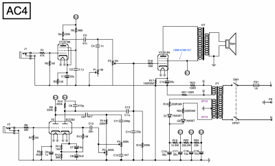
This is what I’ve come up with so far, but I have some thoughts about some things:

I’ve measured the power transformer putting out 271V ac in circuit (288V out of circuit), so it’s about 21V higher than the original one (and the AC4TV one), so I thought the 220R resistors would get it closer to 250V. Have I got that about right or have I thought/calculated it all wrong? (It’s mostly guestimations…)
I found a EZ80 valve is hard to find for not too much money, so I went with a solid state rectifier (as the AC4C1 and AC4TV). I guess that won’t affect the sound very much, or does it?
In the original AC4 schematic, the screen grid is connected directly to the +270V and since the anode HT goes though the output transformer first, shouldn’t that make the screen grid more positive than the anode? Shouldn’t there be a limiting resistor between the B+1 and screen grid?
I’d be happy for any help with this, or please mention if you think I’ve missed something important.
Not because I don’t like how it sounds, more like because -why not?
I’ll be keeping the original circuit in a box so I can put it back if the project goes south… I’ll just be using the cab, speaker and transformers in the new build.
Looking around for schematics I’ve found one for the original AC4 and the AC4TV, so I thought it would be fun to ad a second channel with the AC4TV preamp which is more like the AC30/6 preamp.
This is what I’ve come up with so far, but I have some thoughts about some things:
I’ve measured the power transformer putting out 271V ac in circuit (288V out of circuit), so it’s about 21V higher than the original one (and the AC4TV one), so I thought the 220R resistors would get it closer to 250V. Have I got that about right or have I thought/calculated it all wrong? (It’s mostly guestimations…)
I found a EZ80 valve is hard to find for not too much money, so I went with a solid state rectifier (as the AC4C1 and AC4TV). I guess that won’t affect the sound very much, or does it?
In the original AC4 schematic, the screen grid is connected directly to the +270V and since the anode HT goes though the output transformer first, shouldn’t that make the screen grid more positive than the anode? Shouldn’t there be a limiting resistor between the B+1 and screen grid?
I’d be happy for any help with this, or please mention if you think I’ve missed something important.
Attachments

Last edited:
