6G3 Bias amperage spike

bel Sonique Guitars

TDPRI Member
Joined
Jun 10, 2025
Posts
7
Location
Phoenix
Hi, I’m new here, 6G3 build
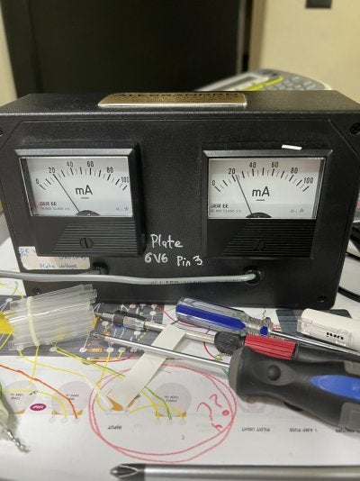
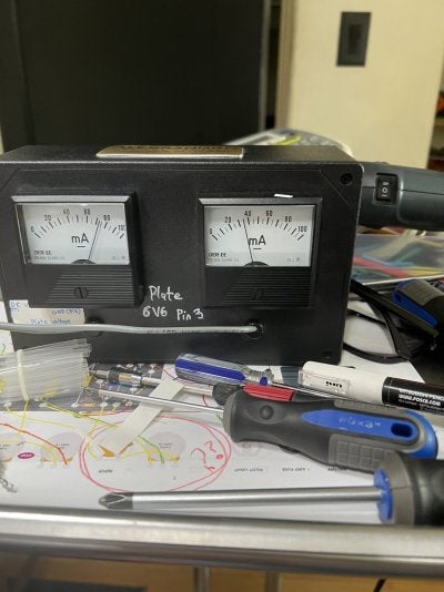
I’m getting a spike of 80ma on valve 4 6v6, when amp is almost dimmed on an open E chord. I can’t audibly hear anything just see it on my meter (see attached pics) valve 5 seems to be where it should. Also note GZ34 420-430V at the plate
Amps biased around 20-21ma
Swapped tubes as well
SPECS: Mojo Tone layout/schematic *added* bias pot, screen and grid resistor 470/1500
PT Hammond 290BX 355V
OT Hammond 1760H 20W

Thoughts?

Thanks all!
 

Attachments

  • IMG_6741.jpeg
    IMG_6741.jpeg
    174.2 KB · Views: 13
  • IMG_6745.jpeg
    IMG_6745.jpeg
    154 KB · Views: 13

Wally

Telefied
Ad Free Member
Joined
Mar 17, 2003
Posts
46,337
Location
Lubbock, TX
Fixed biased circuits draw more current when processing signal than they do at idle, but that is quite a jump. What happens if you the positions of those power tubes? Does the high draw hollow the tube?
 

bel Sonique Guitars

TDPRI Member
Joined
Jun 10, 2025
Posts
7
Location
Phoenix
Fixed biased circuits draw more current when processing signal than they do at idle, but that is quite a jump. What happens if you the positions of those power tubes? Does the high draw hollow the tube?
I did swap tubes and manufactures, same experience on valve 4
 

2L man

Friend of Leo's
Joined
Nov 23, 2020
Posts
4,694
Age
65
Location
Finland
Low E frequency might be inside installed loudspeaker resonance peak where impedance is much higher. Loudspeaker pull less that frequency current and Anode Voltage Swing tips can go very low. Screen voltage stay high and cathode begin to pull current from Screen and most likely you see that current.

After installing new 6V6GT tube pair I have measured about 30VDC over 470 ohm Screen Resistor which mean about 60mA RMS Screen Current. Other 6V6 Screen current was lower. Looking SR voltage loss using oscilloscope Screen Current peaks were 120mA.

If amp has separate Screen Resistors measure DV voltages over them while doind same playing test! Screen current will increase also Screen Dropper Resistor voltage loss but it happen slower because of Filter Electrolyte.

This graph show how Screen Current increase very fast always Anode Voltage swings go low! Good to notice those measures were done having only 250VDC Screen Voltage. Scale is on right and "Ig2 curves" climb on left.

6V6GT-Screen-Current.jpg
 
Last edited:

peteb

Poster Extraordinaire
Joined
Apr 25, 2003
Posts
7,406
Location
Cascadia

How or where are you measuring current ?


Are the two 6V6 seeing the same DC voltages ?

Probably yes since the DC idle bias current is the same on both tubes, 20 mA.


Then I think all you can check is are both tubes getting the same amount of signal ?

And resistances. Do all tube pins measure the same resistance to ground on the two different tube sockets ?


The cause could be odd tube behavior at the limits.

Personally, I don’t think dimed is normal use for that amp.


That amp probably draws 0.4 - 0.5 - 0.6 amps from the wall.


One tube draw an additional 15 mA while the other draws an additional 52 mA. That is drawing at least an extra 67 mA under extremely high load.


Idle 0.5 amps going up to .57 amps under full load is not unheard of at all, or probably not unusual at all. Maybe the other tube’s current is not going up enough.

The amps fuse is 2 A. 0.60 - 0.70 A of current draw from the wall at extreme full power is nothing.


The whole issue is probably not a problem. It is just a little curious.
 
Last edited:

bel Sonique Guitars

TDPRI Member
Joined
Jun 10, 2025
Posts
7
Location
Phoenix
Low E frequency might be inside installed loudspeaker resonance peak where impedance is much higher. Loudspeaker pull less that frequency current and Anode Voltage Swing tips can go very low. Screen voltage stay high and cathode begin to pull current from Screen and most likely you see that current.
so from what you are thinking could just be what it is?
 

2L man

Friend of Leo's
Joined
Nov 23, 2020
Posts
4,694
Age
65
Location
Finland
so from what you are thinking could just be what it is?
I think it is that! I have used for example three to five times higher resistance resistor than OT is wired on output and phenomenon come better "controlled" to oscilloscope measures. Also without loud volume from loudspeaker :)

Just in case you could also veryfy that OT primary wiring is right that it is Center Tab where HV go. Voltage measures from CT to anodes reveal this. Also resistance measures can reveal this. Depending OT primary halfs resistances can be the same but sometimes resistance difference is even 30%. Two halfs resistances should sum between anodes!
 

2L man

Friend of Leo's
Joined
Nov 23, 2020
Posts
4,694
Age
65
Location
Finland
However there reads that Meter current is 6V6 plates pin #3! When signal is amplified Plate Voltage swings very wildly and meter reading can not be trust fully!!! So what I wrote does not apply here!

Connect Meters to Cathodes if you need to know Cathode current during amplifying! They should also have parallel filter capacitors.
 

elpico

Tele-Afflicted
Joined
Sep 14, 2011
Posts
1,987
Location
Vancouver BC
There shouldn't be a drastic difference between the two sides of a push pull amp. There will always be *some* difference, but if the
meter in those images is giving accurate readings you would definitely have a problem that needs to be solved. That would be in the ballpark of 30W dissipation for one 6V6 no?

You should do some work to confirm the measurement is correct because it's all too easy to end up chasing your tail trusting a number on a meter as fact without doing any verification.

If it is real you'll have to do something about it.
 

bel Sonique Guitars

TDPRI Member
Joined
Jun 10, 2025
Posts
7
Location
Phoenix
How or where are you measuring current ?


Are the two 6V6 seeing the same DC voltages ?

Probably yes since the DC idle bias current is the same on both tubes, 20 mA.


Then I think all you can check is are both tubes getting the same amount of signal ?

And resistances. Do all tube pins measure the same resistance to ground on the two different tube sockets ?


The cause could be odd tube behavior at the limits.

Personally, I don’t think dimed is normal use for that amp.


That amp probably draws 0.4 - 0.5 - 0.6 amps from the wall.


One tube draw an additional 15 mA while the other draws an additional 52 mA. That is drawing at least an extra 67 mA under extremely high load.


Idle 0.5 amps going up to .57 amps under full load is not unheard of at all, or probably not unusual at all. Maybe the other tube’s current is not going up enough.

The amps fuse is 2 A. 0.60 - 0.70 A of current draw from the wall at extreme full power is nothing.


The whole issue is probably not a problem. It is just a little curiousThanks that’s a lot to look intoOk, let me gather some more info. I’m using and Alessandro Biasing unit, plugs into the sockets, tubes piggyback

How or where are you measuring current ?


Are the two 6V6 seeing the same DC voltages ?

Probably yes since the DC idle bias current is the same on both tubes, 20 mA.


Then I think all you can check is are both tubes getting the same amount of signal ?

And resistances. Do all tube pins measure the same resistance to ground on the two different tube sockets ?


The cause could be odd tube behavior at the limits.

Personally, I don’t think dimed is normal use for that amp.


That amp probably draws 0.4 - 0.5 - 0.6 amps from the wall.


One tube draw an additional 15 mA while the other draws an additional 52 mA. That is drawing at least an extra 67 mA under extremely high load.


Idle 0.5 amps going up to .57 amps under full load is not unheard of at all, or probably not unusual at all. Maybe the other tube’s current is not going up enough.

The amps fuse is 2 A. 0.60 - 0.70 A of current draw from the wall at extreme full power is nothing.


The whole issue is probably not a problem. It is just a little curious.
Thanks for the explanation , I’m using Allesandro tube bias, plugs into sockets, tubes piggyback bias probes. I’ll take some more measurements from what you’ve stated above.
 

peteb

Poster Extraordinaire
Joined
Apr 25, 2003
Posts
7,406
Location
Cascadia
That is drawing at least an extra 67 mA under extremely high load.

I just duplicated that on my cold biased 63 6G2.

0.33 A wall current at idle rising to 0.40 A under load, volume at 7.


That extra current has to come from somewhere. I believe it is thru the power tubes.


This is my way of looking to see if the current makes sense.


The more correct way is to consider if 72 mA is ok for the tube at the plate voltage. The plate voltage is going to drop when the current goes up.

The tube is not red plating.
 

elpico

Tele-Afflicted
Joined
Sep 14, 2011
Posts
1,987
Location
Vancouver BC
True, seems I'm not paying attention too well today. If the measurements were taken at full output, not idle, then it's likely the side reading low is the one with the problem. Either way you've got a problem that needs investigating if the measurements are correct. Some imbalance is inevitable, but this is not that.
 

bel Sonique Guitars

TDPRI Member
Joined
Jun 10, 2025
Posts
7
Location
Phoenix
For resistance measuring I would measure pin 8 cathode to ground and pin 5 control grid to ground and pin 3 plate to its filter cap (across the OT) and pin 4 screen to its filter cap (across the screen grid resistor).
Thanks for all of that! Played it last 2 days, gonna put on bench tonight to see based on your post where things are
 

bel Sonique Guitars

TDPRI Member
Joined
Jun 10, 2025
Posts
7
Location
Phoenix
Thanks everyone for your thoughts and ideas of what you think is going on, been playing the amp last 2 nights; first time ever really playing it.. Sounded great! I do want to look into everything that everyone has added to this post. Will get on bench tonight for checkup/diagnosis 🤘
 
Top