6G15 Reverb Unit Conversion Help

birdawesome

Tele-Meister
Joined
Aug 17, 2022
Posts
190
Age
30
Location
Houghton, MI
Hey all, I was hoping to get some insight on a current 6G15 build I'm doing. To be more specific, I'm doing a '63 Reverb Unit Reissue conversion over to a hand wired. Wasn't expecting to get anything out of it other than some knowledge and experience, along with a little fun and personal satisfaction.

However, it's been proving to be quite the headache. I started this conversion wanting to utilize the stock transformers, thereby reducing cost. I bought the small parts kit from Mojotone (https://www.mojotone.com/Mojotone-6G15-Blackface-Reverb-Unit-Small-Parts-Kit) so to get the eyelet boards and all the other parts I'd need.

I finished the build, but was having some further trouble. I had a dry signal output, but no reverb. The tank would "crash" if you gave the box a good wallop, but other than that, nothing returning from the reverb tank. So began the troubleshooting process.

Now, since I'd repurposed the PT, choke, and OT, I was maybe starting to have doubts that my transformers would marry well with the Mojotone wiring diagram I used. I think that the PT is made for full wave, and same with the Mojotone, but I'm not 100% sure on that. Furthermore, my PT gives off 260V, which I don't think is problematic necessarily, but I ended up following StewMac's pdf build troubleshooting section to help me with the troubleshooting process (from what it looks like, the StewMac build just looks like a cleaner, less redundant version of the MojoTone build as far as grounding is concerned). In their guide, the voltages they said to look for coming off of the power section/filter caps would be 420V...I don't think mine was any higher than the 260V or maybe 300V...I can't quite remember, but it was much lower. I don't know if this is problematic or not necessarily considering our PT specs could just be differ, and could be negligible regarding the circuit, but figuring out these kinds of things are a big reason why I wanted to do this in the first place.

Regarding the OT, their diagram only has a blue, red, and yellow wire coming off, whereas mine has a blue, red, green, and black. The way the RI unit was wired initially was with the green connecting to the positive terminal off the RCA jack, and the black going to ground, which I figured I should just follow suit here. The StewMac diagram only has the yellow going to positive, with no wiring connecting to ground. So those are the big differences here. However, something I just discovered that is kind of concerning to me is that when I have my black wire grounded, the green is continuous with it...this seems weird to me. From what my intuition tells me, they both seem to be coming off the same winding on the transformer anyways, but wouldn't this be just sending any signal coming back from the pan straight to ground? Or is this line of thinking incorrect? If not, is the signal jumping off the winding onto the next along the way to the black lead, explaining why this would still work? Or do I possibly have a short?

Furthermore, my voltages on V1 were looking right for the most part, but my voltages on V2 were way off. Most pins weren't reading anything at all. It's obvious to me that something in this path is wrong, but I can't/couldn't explain it. I've since out of frustration decided to strip the entire unit, suck all the solder out of the joints, and test every capacitor with my multimeter again just to see if I had a bad cap or something...all the caps looked fine, which I was kind of hoping wasn't the case, just to make sense of what's going on. I bought all new caps to move forward with, considering my leads were all cut short on the old ones now, and I wanted to do it nice and clean. I've replaced all the orange drops with SoZo's, which are rated at 500V instead of the 600V of the orange drops (this should be fine right? To my knowledge no voltages get that high anyways).

Anyhow, I've essentially begun the build from scratch in a way, but these transformers in particular really got me thinking. Sorry for the long post, but this has been plaguing me for a while. Between working full time and going to school full time I don't have much free time to work on this thing, so it's especially frustrating when I spend any free time I do have on this unit without anything to show for it. Any help/insight that you guys could give me would be GREATLY appreciated.

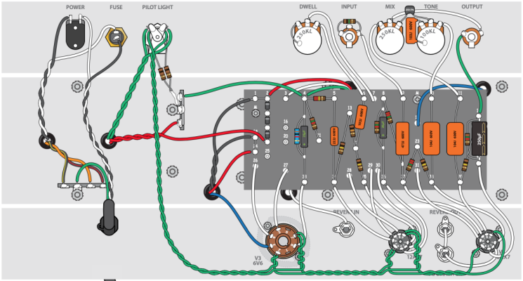
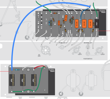
I've attached both of the diagrams I've been using, if that helps anyone make sense of what I've been doing. Keep in mind, I started with the MojoTone, but I'm redoing the whole thing using StewMac's because it looks like the more elegant of the two.

Thanks in advance!
 

Attachments

  • MojoTone Diagram.png
    MojoTone Diagram.png
    302.6 KB · Views: 297
  • MojoTone Filter Section.png
    MojoTone Filter Section.png
    34.5 KB · Views: 197
  • StewMac Diagram.png
    StewMac Diagram.png
    446.7 KB · Views: 181
  • StewMac Filter Section.png
    StewMac Filter Section.png
    436.5 KB · Views: 247

glenlivet

Friend of Leo's
Joined
Nov 7, 2018
Posts
2,259
Location
Marco.......Polo......
do you have a schematic you are working from? The original 6g15 schematics show about 300v after the diodes. So...the 260v you were seeing *seems* about correct. (?)
The fact that you were getting a dry signal, and a crash out of the tank, makes me believe you just had a problem somewhere in the wet signal path.
you should watch this:
 

Freeman Keller

Doctor of Teleocity
Ad Free Member
Joined
Aug 22, 2018
Posts
15,880
Age
80
Location
Washington
Bird, for what it is worth I just finished assembling a Mojotone 6G15 reverb. During my check out I had some of the correct bias voltages but some that were very wrong. After staring at the eyelet board wiring diagram long enough I finally discovered that there was one jumper on t he back of the board that I had not installed. Adding it to the front brought all the bias voltages in line with the schematic and I've determined that t he unit is correctly working. I'm currently building up steam to make a box for it.

IMG_7500.JPG


IMG_7501.JPG


I was frankly disappointed in the instructions with the kit - it was not obvious the order of assembly or the lengths of wires that should be left to go between the eyelet board and various fixed components. It is also very tight clearances to connect some of the wires, particularly to tube sockets.

My suggestion is to keep comparing the schematic with the wiring diagrams, particularly the back side of the board.

Good luck
 

Snfoilhat

Tele-Afflicted
Joined
Apr 8, 2016
Posts
1,917
Age
44
Location
Oakland, CA
I would hold off using the original 6G15 schematic until you have a power supply working as expected. The way to ensure that is to start with what you know you have, the '63 reissue parts.
63_Reverb_Schematic.png

You can de-tune this back to 6G15 in some respects if you want to (like the ground lift), but this is the map to getting the transformers you have to work. Mojotone and Stewmac are only going to provide layouts for the transformers they sell/recommend. They may be very similar or not similar at all, so I would either do the homework of comparing the transformer specs to determine how similar, or put them both aside until the power supply is done. 420 B+ sounds like some kind of hack to use off the shelf black panel Champ parts. Gonna be tough on the 6K6GT reverb driver tube. Good luck
 

sudogeek

Tele-Holic
Joined
Sep 9, 2016
Posts
736
Location
Palm Beach FL
You are hearing the crash after hitting the tank - so the reverb return side is working. You have a problem between the wiring from the input jack to the pin2 of V1 (the 12AT7) and the input transducer in the reverb tank. You just need to work backwards. First, switch to a different reverb tank and see if you get wet signal. If not (for a known good tank), there the problem is more upstream - perhaps the send cable, the reverb send jack, the reverb transformer (which you term the output transformer), or the 6V6/6K6 tube, and so on going backwards. Check the voltages and wiring carefully. You will probably spot the problem

The easy way, though, is to use a signal generator and an oscilloscope, inject a standard signal into the input jack and then test at the indicated test points (marked as 'TP' on the schematic) for the signal. Working from V1 pin2, move downstream until you lose the signal. That's how I would do it.
 

birdawesome

Tele-Meister
Joined
Aug 17, 2022
Posts
190
Age
30
Location
Houghton, MI
do you have a schematic you are working from? The original 6g15 schematics show about 300v after the diodes. So...the 260v you were seeing *seems* about correct. (?)
The fact that you were getting a dry signal, and a crash out of the tank, makes me believe you just had a problem somewhere in the wet signal path.
you should watch this:

I was really just working off of the wiring diagrams, but referencing the original Fender schematic for my voltages. Maybe I should be wary of looking for exact voltages if this is the case.

Thanks for that video. It looks like it may be very helpful for me to sit down and watch it.
 

birdawesome

Tele-Meister
Joined
Aug 17, 2022
Posts
190
Age
30
Location
Houghton, MI
Bird, for what it is worth I just finished assembling a Mojotone 6G15 reverb. During my check out I had some of the correct bias voltages but some that were very wrong. After staring at the eyelet board wiring diagram long enough I finally discovered that there was one jumper on t he back of the board that I had not installed. Adding it to the front brought all the bias voltages in line with the schematic and I've determined that t he unit is correctly working. I'm currently building up steam to make a box for it.

View attachment 1019585

View attachment 1019586

I was frankly disappointed in the instructions with the kit - it was not obvious the order of assembly or the lengths of wires that should be left to go between the eyelet board and various fixed components. It is also very tight clearances to connect some of the wires, particularly to tube sockets.

My suggestion is to keep comparing the schematic with the wiring diagrams, particularly the back side of the board.

Good luck
Glad to see you got it working! This build really could've used some better instructions...just a little something extra. But, thanks for that advice. It's very likely I could've missed a jumper somewhere, but too late for that now lol. I'm just trying to make sure I go extra slow this go around so that I don't make that mistake.
 

birdawesome

Tele-Meister
Joined
Aug 17, 2022
Posts
190
Age
30
Location
Houghton, MI
I would hold off using the original 6G15 schematic until you have a power supply working as expected. The way to ensure that is to start with what you know you have, the '63 reissue parts.
View attachment 1019589
You can de-tune this back to 6G15 in some respects if you want to (like the ground lift), but this is the map to getting the transformers you have to work. Mojotone and Stewmac are only going to provide layouts for the transformers they sell/recommend. They may be very similar or not similar at all, so I would either do the homework of comparing the transformer specs to determine how similar, or put them both aside until the power supply is done. 420 B+ sounds like some kind of hack to use off the shelf black panel Champ parts. Gonna be tough on the 6K6GT reverb driver tube. Good luck
Thank you, this is very helpful information. Not sure why I didn't think to reference the Fender RI schematic to make sure I was getting the *correct* specs for their components (being the transformers). I'll look into the specs of their transformers some more to see what kind of differences I'm working with here. I have seen that people have used some widely varying PT specs though, so it seems like maybe the power section would be bringing everything to a usable voltage?
 

birdawesome

Tele-Meister
Joined
Aug 17, 2022
Posts
190
Age
30
Location
Houghton, MI
You are hearing the crash after hitting the tank - so the reverb return side is working. You have a problem between the wiring from the input jack to the pin2 of V1 (the 12AT7) and the input transducer in the reverb tank. You just need to work backwards. First, switch to a different reverb tank and see if you get wet signal. If not (for a known good tank), there the problem is more upstream - perhaps the send cable, the reverb send jack, the reverb transformer (which you term the output transformer), or the 6V6/6K6 tube, and so on going backwards. Check the voltages and wiring carefully. You will probably spot the problem

The easy way, though, is to use a signal generator and an oscilloscope, inject a standard signal into the input jack and then test at the indicated test points (marked as 'TP' on the schematic) for the signal. Working from V1 pin2, move downstream until you lose the signal. That's how I would do it.
Gotcha. That all makes sense. Thanks for the methodology. Unfortunately I don't have an oscilloscope at my home, but do at work. If worse comes to worst and this second go around with the rebuild results in more issues I'll likely bring the unit in and start prodding around. Either that or I'll bite the bullet and buy my own...it'd be nice to have around anyhow.

Thanks for the information!
 

Freeman Keller

Doctor of Teleocity
Ad Free Member
Joined
Aug 22, 2018
Posts
15,880
Age
80
Location
Washington
Here is the jumper that I had to add - the white wire running diagonal from the 100K/10K to the 2.2M/100K. There are yellow wires on the back of the board but somehow I miss this and once everything was in the chassis there is no way I wanted to take it apart.

20220821_134333.jpg


During trouble shooting I just measured the voltage to ground at every point on the board and wrote it on the wiring diagram. Then went to the schematic which has some of the bias voltages listed and compared - some were spot on, some were pretty wonky. When I was pretty sure this was missing I clipped a jumper between the two points, everything got good. Made the jumper permanent and plugged it in.

Hope yours turns out to be that easy.
 
Last edited:

Snfoilhat

Tele-Afflicted
Joined
Apr 8, 2016
Posts
1,917
Age
44
Location
Oakland, CA
I'm not here to drag kit retailers, but I do think it's appropriate to approach everything with a bit of skepticism. Consider that in 1963, Fender used half-wave rectification (the string of three silicon diodes on one side of the high voltage primary, with the other side of the primary grounded), and that when Fender designed the '63 Reissue, they changed to full-wave bridge. Presumably, Fender can source any transformers they want.

The Mojotone and the Stew Mac look to be copied from the original 6G15 with it's half-wave rectifier, but how much do we know about the power transformers? I see a basic wiring diagram available for the mojo, but not the details you'll see may be relevant here.

Here's food for thought from Designing Power Supplies for Tube Amplifiers 2nd ed.:

"A significant problem with this [half-wave] rectifier is that the average current flowing in the transformer is also unidirectional, leading to some amount of net DC flux in the transformer core. Modern power transformers are normally designed to run strictly on pure AC; even a little DC flux can quickly push them into severe saturation and overheating. Half-wave rectifiers were commonly used in valve appliances years ago, but the power transformers were specially designed to cope with this DC flux. Do not fall into the trap of copying an old circuit without this provisio in mind. In a modern setting, half-wave rectifiers are only safe for very low-current supplies, or best avoided altogether."
 
Last edited:

birdawesome

Tele-Meister
Joined
Aug 17, 2022
Posts
190
Age
30
Location
Houghton, MI
Here is the jumper that I had to add - the white wire running diagonal from the 100K/10K to the 2.2M/100K. There are yellow wires on the back of the board but somehow I miss this and once everything was in the chassis there is no way I wanted to take it apart.

View attachment 1019627

During trouble shooting I just measured the voltage to ground at every point on the board and wrote it on the wiring diagram. Then went to the schematic which has some of the bias voltages listed and compared - some were spot on, some were pretty wonky. When I was pretty sure this was missing I clipped a jumper between the two points, everything got good. Made the jumper permanent and plugged it in.

Hope yours turns out to be that easy.
Woah that's so weird...the one I'm looking at doesn't have that bridge on it. I'm looking at what looks to be labelled Revision 4. Are you using a different version? I wonder if this is what's been plaguing me all along.
 

Freeman Keller

Doctor of Teleocity
Ad Free Member
Joined
Aug 22, 2018
Posts
15,880
Age
80
Location
Washington
My schematic is Revision 1 but I pointed out an error (cap value) and their web page now has Revision 2. The wiring diagram is Revision 5. Both can be down loaded.

That was the only documentation included with their kit, marginally adequate when compared with what others are providing.
 

birdawesome

Tele-Meister
Joined
Aug 17, 2022
Posts
190
Age
30
Location
Houghton, MI
My schematic is Revision 1 but I pointed out an error (cap value) and their web page now has Revision 2. The wiring diagram is Revision 5. Both can be down loaded.

That was the only documentation included with their kit, marginally adequate when compared with what others are providing.
Oh I see. I got a little worried when I saw REV 5, since I've been using 4, but it looks like the only different to my eye atm is just the power switch.
 

birdawesome

Tele-Meister
Joined
Aug 17, 2022
Posts
190
Age
30
Location
Houghton, MI
Just a little update:

Here's where I'm currently at. Sorry the lighting isn't great, it got dark and my lamps aren't very adequate. Have it all back together expect for V1 and V2, which I wanted to start clean using new tube sockets with. My wiring is cleaner this time around, and I triple checked all of my connections...if I've missed something this time my optometrist is up for a visit. Hoping once I get these sockets installed and wired it'll be smooth reverb-ing!
IMG_2112.JPG
IMG_4983.JPG
IMG_2657.JPG
 

birdawesome

Tele-Meister
Joined
Aug 17, 2022
Posts
190
Age
30
Location
Houghton, MI
Could be something else, but a common problem is the RCA jacks/cables.
I did replace the cables, as well as check continuity with my old ones. But didn’t replace the jacks themselves. It’s possible the reverb send jack was the issue, but I’ve since replaced them anyways. If my unit works on first power up once I finish it I’ll never know what the cause was initially, but I won’t be complaining.
 

Snfoilhat

Tele-Afflicted
Joined
Apr 8, 2016
Posts
1,917
Age
44
Location
Oakland, CA
@birdawesome , so you’re changing the ‘63 RI bridge rectifier to the older 6G15/mojo/StewMac rectifier?

I’m curious to see when yours is done what the voltages look like and if the PT feels warmer than expected while its running
 
Top