5F2-A roll-your-own DIY BOM and ideas

  • Thread starter chas.wahl
  • Start date
  • This site may earn a commission from merchant affiliate links like Ebay, Amazon, and others.

chas.wahl

Tele-Holic
Joined
Dec 8, 2012
Posts
977
Location
NYC
In response to interest expressed in another thread (about whose kit to buy) for a DIY Bill of Materials, I've put together something like that, and put the files into a folder on DropBox, so that it's easy to modify the materials and upload when people have pointed out all my errors and omissions:


There are 8 files in the folder:
1 | 5F2-A bill of materials.xlsx - my Excel spreadsheet containing items 2 and 4–6 below, plus a Calculators sheet I use occasionally
2 | General Notes 5F2-A BOM.pdf
3 | Fender 5F2-A layout marked up.pdf
4 | 5F2-A BOM.pdf
5 | Wire Gauges.pdf
6 | Hdw Info.pdf
7 | 5F2-A alt head schem.pdf
8 | 5F2-A alt head layout.pdf

The last two are my personal take on making changes to the layout (based largely on ideas from Merlin Blencowe, and adding features that may or may not be stupid/foolhardy ideas. They're included simply to provide some notions about where one might go, and the additional components are included and identified in both the XLS and PDF versions of the BOM.

If anyone has trouble accessing these, just let me know.
 

tele_savales

Tele-Afflicted
Joined
Apr 30, 2018
Posts
1,958
Age
59
Location
Brooklyn, Joey!
In response to interest expressed in another thread (about whose kit to buy) for a DIY Bill of Materials, I've put together something like that, and put the files into a folder on DropBox, so that it's easy to modify the materials and upload when people have pointed out all my errors and omissions:


There are 8 files in the folder:
1 | 5F2-A bill of materials.xlsx - my Excel spreadsheet containing items 2 and 4–6 below, plus a Calculators sheet I use occasionally
2 | General Notes 5F2-A BOM.pdf
3 | Fender 5F2-A layout marked up.pdf
4 | 5F2-A BOM.pdf
5 | Wire Gauges.pdf
6 | Hdw Info.pdf
7 | 5F2-A alt head schem.pdf
8 | 5F2-A alt head layout.pdf

The last two are my personal take on making changes to the layout (based largely on ideas from Merlin Blencowe, and adding features that may or may not be stupid/foolhardy ideas. They're included simply to provide some notions about where one might go, and the additional components are included and identified in both the XLS and PDF versions of the BOM.

If anyone has trouble accessing these, just let me know.
Unbelievable! Thanks for posting.
 

King Fan

Doctor of Teleocity
Ad Free Member
Joined
Jan 1, 2013
Posts
12,183
Location
Salt Lake City
Amazing and thoughtful, @chas.wahl .

Last thing I'd suggest is that you should put any more effort into this public service project. You've done a ton of work, and this won't add usefully to your BOM.

But I'm wondering if we all (not you, personally, you deserve a vacation and a rum drink with a little umbrella :)) would be able share stripped-down, text-only BOMs inline on the forum. I was looking thru my old 5F2a folder the other day (re that other build thread) and noticed I'd downloaded a Weber BOM into Excel a million years back. It's obviously outdated and idiosyncratic (copper cap) and goofy (wire nut?), but I was able to delete the tedious part number column and copy/paste the basic list as text.

Qty Description
1 Power Transformer USA EU
1 Cabinet, 5F2A, complete
1 Speaker, Signature Series, 10", 8 ohm, AlNiCo, S type
4 Nut, #8-32 with integral washer (for mounting speaker)
1 5F2A Chassis, brass plate, fiber board front and back
1 Transformer, output
1 Copper Cap Rectifier
1 Vacuum tube
1 Vacuum tube
1 Power cord, cut end
1 Kit, cloth covered wire, 5F2A
2 Knob, black, chicken head, flat top
1 Fuse, 1 amp
2 Tube socket, octal
1 Tube socket, 9 pin
2 Clamp, octal
8 Bolt, machine, #4-40x3/8, with nut and star washer
4 Spacer, nylon, for SKT8
1 RCA jack, chassis mount, diamond fiber base
1 RCA plug, male, cable mount
1 Fuseholder
2 Bolt, chassis, tweed style, chrome, with nut
1 Pilot light, red
1 Strain relief
1 Carling Switch, toggle, panel mount, SPST
2 Chassis mount phone jack, shorting
2 9/16" OD Chassis Grommets
2 Potentiometer, 1 meg audio
1 Wire Nut, small
2 Fiber Board Mounting Screws

1 Capacitor, 500pF, 500 volts
2 Capacitor, 25uF, 25 volts
2 Capacitor, 8uF, 450 volts
2 Capacitor, 16uF, 450 volts
1 Capacitor, .0047uF, 630 volts
2 Capacitor, .022uF, 630 volts
2 Resistor, 1.5K, 1/2 watt
1 Resistor, 22K, 1/2 watt
2 Resistor, 68K, 1/2 watt
2 Resistor, 100K, 1/2 watt
1 Resistor, 220K, 1/2 watt
1 Resistor, 1M ohm, 1/2 watt
1 Resistor, 10K, 2 watt
1 Resistor, 22K, 2 watt
1 Resistor, 470 ohms, 5 watt
 

chas.wahl

Tele-Holic
Joined
Dec 8, 2012
Posts
977
Location
NYC
The forum is welcome -- it certainly gives me a lot of enjoyment; and I actually learned a thing or two through the excercise of putting those things together.

If anyone can't deal with the XLSX spreadsheet file and would prefer CSV, I could export and upload that.
 

King Fan

Doctor of Teleocity
Ad Free Member
Joined
Jan 1, 2013
Posts
12,183
Location
Salt Lake City
can't deal with the XLSX spreadsheet file

D'oh, sorry, @chas.wahl , I was puzzled; I'd thought the first 'page' of your attachment was just text, and all the rest were PDFs. Who can't deal with text and PDFs? Double duh. Thinking about it again this morning, I went back and realized the Excel page has multiple "sheets" -- is that what MS calls 'em? I've worked with Excel for years, but almost gave up on sheets, cuz the little tabs at the bottom of the page were so forgettable. For anyone else who missed 'em, check these out. *Tons* of info:

1675697339708.png
 

Heyhey

TDPRI Member
Joined
Jan 24, 2021
Posts
92
Age
54
Location
Edmonds, WA USA
Oh man, this is a huge help. I've got a chassis and transformers for a 5F2A on their way as I write this. Thanks!
 

tonebrulee

Tele-Meister
Joined
Sep 6, 2008
Posts
130
Location
Massachusetts
In response to interest expressed in another thread (about whose kit to buy) for a DIY Bill of Materials, I've put together something like that, and put the files into a folder on DropBox, so that it's easy to modify the materials and upload when people have pointed out all my errors and omissions

hey @chas.wahl - awfully nice work there, greatly appreciated. i'm getting ready for a scratch 5F2-A head build and have been thinking about chassis/mounting options. simplest would be a commercial chassis front-facing with the tubes horizontal so wondering what folks thoughts might be with that? don't especially like it both for the physical stress on the tube pins/sockets and for the increased depth of the head cabinet. i suppose it might be possible to cut new tube sockets on the wide surface for vertical tube orientation - anybody done that? i'll be custom building the wood cab and so another option might be flat sheet aluminum that just slides into groove or sits on runners on the interior sides of the cab, cutting the tube socket and tranny openings by hand and either mounting the controls on a front facing wood panel, or maybe another piece of sheet aluminum mounted to the front facing wood panel. thoughts?

fyi - example here of a head build using a commercial chassis with horizontal tubes
 

chas.wahl

Tele-Holic
Joined
Dec 8, 2012
Posts
977
Location
NYC
My only advice about mounting tubes horizontally is (just from memory, which may be deficient/selective) that I've run across one or two datasheets where socket pins down or socket pins up are "permissible" but socket on the side is either no go or some element has to be facing some direction. Cannot remember specifics. Seems to me that "sidearm" mounting is uncommon, I think it's safe to say that.

You want to make sure that those tubes aren't close enough to anything flammable, and have a decent clear dimension around them for some airflow, to promote heat dissipation. Remember that for installing and removing tubes, hand access and a bit of wiggling is involved; so don't make that any more difficult than it has to be.

Another thing to consider is that the chassis provides a measure of shielding to the circuit, which is why a) most chassis are conductive metal and b) why, presumably, the bog-standard Tweed chassis (a.k.a. "gopher coffin") has 5 sides, and is often completed by the cover panel having aluminum or copper tape or facing.

If you're thinking of doing your own chassis fabrication, modifications or finishing, then access to a drill press is key, for control and safety; and I'd counsel sticking to aluminum as a material. Steel is hard (even at 0.050"/2 mm thickness), stainless steel is even harder, and aluminum is a much better conductor than either of them. I can do holes up to 3/4" diameter with a step drill bit, but above that I think I'd invest in a sheet metal "knockout" punch or two ($$) for openings like octal sockets; or else work to a scribed line with hand tools and a Dremel for final trimming -- but that's a lot of work!

To tell the truth, I found it well worth the (very reasonable) cost to put together a clear drawing of what I wanted, in terms of a custom chassis, and have Terry at Seaside Music in NS CA ( seasidechassisdesign.com ) put it together. He doesn't do anything holes-wise except octals, novals and transformer and IEC cutouts, but I was fine with that, and he'll work in both 12 (0.080") and 14 (0.060") gauge aluminum as you prefer. Fabrication quality is excellent.

Other than those points, innovate away! It's supposed to be fun.
 
Last edited:

gabasa

Tele-Afflicted
Joined
Jan 29, 2018
Posts
1,518
Location
Toronto, ON
In response to interest expressed in another thread (about whose kit to buy) for a DIY Bill of Materials, I've put together something like that, and put the files into a folder on DropBox, so that it's easy to modify the materials and upload when people have pointed out all my errors and omissions:


There are 8 files in the folder:
1 | 5F2-A bill of materials.xlsx - my Excel spreadsheet containing items 2 and 4–6 below, plus a Calculators sheet I use occasionally
2 | General Notes 5F2-A BOM.pdf
3 | Fender 5F2-A layout marked up.pdf
4 | 5F2-A BOM.pdf
5 | Wire Gauges.pdf
6 | Hdw Info.pdf
7 | 5F2-A alt head schem.pdf
8 | 5F2-A alt head layout.pdf

The last two are my personal take on making changes to the layout (based largely on ideas from Merlin Blencowe, and adding features that may or may not be stupid/foolhardy ideas. They're included simply to provide some notions about where one might go, and the additional components are included and identified in both the XLS and PDF versions of the BOM.

If anyone has trouble accessing these, just let me know.
That was very cool of you to do.
 

Lowerleftcoast

Poster Extraordinaire
Joined
Dec 30, 2019
Posts
7,460
Location
california
Wha...wait... @chas.wahl up until now I was under the impression I was conversing with a real person. Please confirm you are not a robot by placing a check on every picture that contains a Telecaster.
 

Lowerleftcoast

Poster Extraordinaire
Joined
Dec 30, 2019
Posts
7,460
Location
california
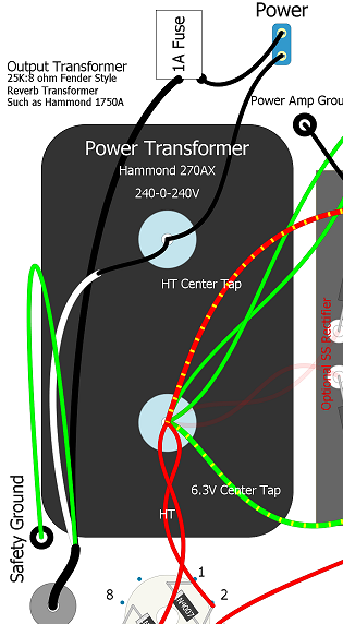
Rob shows a different power cord wiring. Safety first. The hot wire should be the one that has a fuse and is switched. Yes the European standard of switching both hot and neutral wires can be implemented.

Champ_Micro_Layout-1.png
 

Lowerleftcoast

Poster Extraordinaire
Joined
Dec 30, 2019
Posts
7,460
Location
california
Are you talkin' to me
When I looked at the *Dropbox* the only layout was the original Fender with the red highlights. Today the additional layouts are displayed. I thought I was being helpful. Sorry.

I have to say, I appreciate all the work you have put into this.
Good job!
 

chas.wahl

Tele-Holic
Joined
Dec 8, 2012
Posts
977
Location
NYC
I ran across an error in the BOM I posted; can no longer edit first post, so here goes . . .
ERRATUM: what's listed as R5 (resistor 220k 1W) is described as V1b grid leak, when it's actually the grid leak for the 6V6 power tube! I've fixed that in the stuff uploaded to Dropbox.

Sorry for the interruption -- Carry on . . .
 
Top