5 W build suggestions

  • Thread starter furor_furor
  • Start date
  • This site may earn a commission from merchant affiliate links like Ebay, Amazon, and others.

Crowe Baaah

Tele-Holic
Gold Supporter
Joined
Aug 11, 2024
Posts
562
Age
44
Location
PA
I have a Hammond CAX90, but to gain some space in my chassis, I am considering a toroidal alternative, which I would hang vertically from the chassis.

I think a toroid is a great idea since with its reduced magnetic field, it will tend to minimize SE ended hum. Since with a SE amp, there is no “sag” to worry about missing out on with a solid-state rectifier, it means you don’t lose any tonal characteristics with this approach, and also that you can be aggressive with filtering to get rid of hum (not so with a tube rectifier, where filter size is capped based on tube choice). I have a a SE Champwreck with diode rectifier using an 80uF/47uF first and second stage filter and it is dead quiet (I should note that with my original schematic calling for 47/47 uf initial filters, there was still a little hum with my traditional Heyboer PT).

On transformers, what’s your target B+? I’ll do some quick example math, but you should double check me and confirm with smarter people on this forum than me before building yours. For example, I think for a 6V6 anywhere 350 - 400 VAC is good. For your 260-0-260 PT, maybe you get loaded B+ around 350V. I think you’d probably get a bias current of around 35-45 mA with a 470-510 ohm cathode resistor, and that would get you more or less where you want to be (~100% bias).

For reference, I just put an Antek 1T-230 (https://www.antekinc.com/as-1t230-100va-230v-transformer/) into this circuit (https://www.tdpri.com/threads/voxish-new-build.1178147/post-13022487) and ended up with a loaded “undropped” voltage of 320 - 330 VDC (I had some dropping/sag resistors in the circuit that brought it down to around 285 VDC for B+).
 
Last edited:

furor_furor

TDPRI Member
Joined
Nov 22, 2024
Posts
83
Age
55
Location
yes
On transformers, what’s your target B+? I’ll do some quick example math, but you should double check me and confirm with smarter people on this forum than me before building yours. For example, I think for a 6V6 anywhere 350 - 400 VAC is good. For your 260-0-260 PT, maybe you get loaded B+ around 350V. I think you’d probably get a bias current of around 35-45 mA with a 470-510 ohm cathode resistor, and that would get you more or less where you want to be (~100% bias).
Well, this is where I'm struggling. I more or less understand drawing loadlines, but when to choose what. I thought that higher voltage gives more headroom/cleaner sound, lower voltage earlier break-up, but this doesn't seem to be entirely true? I read that lower voltage would give you a more dynamic sound, and you don't need that high a voltage. I'll try to find the source.

If I look at the values on the datasheet it says
250V (Ua) and Ia 45 mA as typical values, with a max of 500 V as a pentode. So I thought the 30VA (200V) PT would be ok (since 2L man, and I think Mountainhick, used one, too). I know they can handle more than they specify (amps), but maybe larger is safer. Then I would go for ~350 V, yes. I was just curious if I could manage with a smaller one.

Thanks for the input!
 

guitarmikey

Tele-Afflicted
Joined
Dec 30, 2012
Posts
1,421
Location
Bucharest
Here my modded 5E3 made by a friend, adding tone & gain controls. Great sounding!
2019-09-22 11.09.51.jpg
2019-09-22 11.09.25.jpg
 

2L man

Friend of Leo's
Joined
Nov 23, 2020
Posts
4,693
Age
65
Location
Finland
Hi all,

back to business! I wasn't able to read and prepare as much as I intended the last months, but I finally have some 'headroom'. I have drawn/designed some parts of the circuit/layout, which I will post along the way. I'm organizing my questions and will post them in chunks, to avoid overloading the posts.

Quick recap: I gutted a Yamaha HY-10G III 25W solid state amp. I want to build a '5F2A/GA5' with liftable blackface TB-tone stack, cathode bias tremolo and 'Silverlake' reverb (no transformer). I don't know if it will all be possible, since there's not that much space. Anyway, it's a try, and if necessary I'll leave the reverb, but I would like a tremolo.

I will have 2x 12AX7 (preamp + tremolo) and 1x 12DW7 (reverb), and a 6v6.
If I calculated correctly, I would need 1.4 A heater current and 0.0665 A HV current.

I have a Hammond CAX90, but to gain some space in my chassis, I am considering a toroidal alternative, which I would hang vertically from the chassis.

I'm considering 2 alternatives for now:

a 200 V @0.085 A + 6.3 V @2A --> RMS of 282.84 V under full load, but no centre taps (nor heater, nor secondary) (I think this is the same @2L man used in his build)

or a

260-0-260 V @0.1 A (~368 V RMS) + 3.15-0-3.15 @3 A.

If I understand correctly, 3.15-0-3.15 is basically just 6.3 V, right?

Is the first one (30VA) too tight for the application? I will use diode rectification.
If these are Tube Town Todoid PTs, yes I have used 30VA for 6V6 SE amp. I did not find final measures but I recall about 45mA bias the HV was about 275VDC. About 5V loss to OT primary and 20V to cathode resistor Anode-Cathode voltage was about 250VDC. HV current is above max safe what 85mAAC can supply but it has not blown ;)

TT sell two 250VAC Toroids which allow to build more RC filters for HV.

80VA Toroid is nice PT if you want to use Tube Rectifier!

250VDC/45mA/4k loadline is 5W for TD10%. I was not able to print numeric data to one page :(

Screenshot_20250807_105822_Chrome.jpg
 
Last edited:

elpico

Tele-Afflicted
Joined
Sep 14, 2011
Posts
1,987
Location
Vancouver BC
Well, this is where I'm struggling. I more or less understand drawing loadlines, but when to choose what. I thought that higher voltage gives more headroom/cleaner sound, lower voltage earlier break-up, but this doesn't seem to be entirely true? I read that lower voltage would give you a more dynamic sound, and you don't need that high a voltage. I'll try to find the source.

"Headroom" is just output power. There's unfortunately no free lunch that makes a 5w amp with a 350V B+ have more headroom than a 5w amp with a 300V B+. Would be nice, but 5w is 5w regardless of how you make it.

You just need a transformer set that can work together. You wouldn't pick the highest impedance output transformer available and pair it with an unusually low voltage power transformer for example.
 

2L man

Friend of Leo's
Joined
Nov 23, 2020
Posts
4,693
Age
65
Location
Finland
Well, this is where I'm struggling. I more or less understand drawing loadlines, but when to choose what. I thought that higher voltage gives more headroom/cleaner sound, lower voltage earlier break-up, but this doesn't seem to be entirely true? I read that lower voltage would give you a more dynamic sound, and you don't need that high a voltage. I'll try to find the source.

If I look at the values on the datasheet it says
250V (Ua) and Ia 45 mA as typical values, with a max of 500 V as a pentode. So I thought the 30VA (200V) PT would be ok (since 2L man, and I think Mountainhick, used one, too). I know they can handle more than they specify (amps), but maybe larger is safer. Then I would go for ~350 V, yes. I was just curious if I could manage with a smaller one.

Thanks for the input!
Output Power is a sum of Anode Voltage Swing and Anode Current Swing. Basically HV define AVS and OT impedance ACS. However 6V6 is very old tube design ** and its Anode Current often limit AVS Clipping when both Swings "collide" to Control Grid 0V line. It is defines as A1 operation for Single Anded (AB1 for Push Pull) where CG does not climb higher that the Cathode Voltage is. Its where CG begin to pull current and Capacitor Coupled Driver stop working when positive tips of Drive Signal just charge CC to higher voltage. Then happen "Bias Shift". Higher Drive Signal Amplitude necative phases will go more negative. In SE negative phase will clip more. Typically Champ Loadline Operating (Bias) Point is to the right of "optimum" so negative phase on right has already Clip. In Push Pull the Bias Shift produce Blocking Distortion.

** 6V6 is very sturdy tube type and in guitar amps can function using Higher Anode and Screen Voltages pulling more current and producing more power than datasheet "succest". Distortion is high but luckily often Distortion sound sweet :)
 
Last edited:

furor_furor

TDPRI Member
Joined
Nov 22, 2024
Posts
83
Age
55
Location
yes
TT sell two 250VAC Toroids which allow to build more RC filters for HV.

80VA Toroid is nice PT if you want to use Tube Rectifier!
If the 80VA (260V) is overkill, then one of those 250V are a safer option than the 200V. I see 3 different ones. I think I would go for the 50VA, then.
  • Sec 1: 250 V @ 0,12 A
  • Sec 2: 6,3 V @ 3 A
so I will need artificial centre taps.

I see no differences but the size with the 62VA, which has a larger diameter than the 260V 80VA, so I'd stick with the 50VA. The price difference with the 80VA compensates for the shipping. Ok, I'll finish my shopping tomorrow ;)
 

furor_furor

TDPRI Member
Joined
Nov 22, 2024
Posts
83
Age
55
Location
yes
I was planning to just use 2 diodes for the rectification, but since there will be no centre tap on the HV, should I do a bridge rectifier, or add 2 diodes from ground?
I sometimes see 2 x 2 diodes in series. What's the benefit? Is is just to lower the HV with some volts?
 

2L man

Friend of Leo's
Joined
Nov 23, 2020
Posts
4,693
Age
65
Location
Finland
I was planning to just use 2 diodes for the rectification, but since there will be no centre tap on the HV, should I do a bridge rectifier, or add 2 diodes from ground?
I sometimes see 2 x 2 diodes in series. What's the benefit? Is is just to lower the HV with some volts?
You need artificial CT for Filament Coil. Bridge Fectifier for HV from single coil does not need CT! How Bridge is connect define DC polarity so pay attention there because only one is correct :) One connection make negative voltage and two will blow the PT.

I have that 50VA Toroid in Bridge Rectified EL84 TMB Push Pull and it has not blown but I have played dimed only briefly! Amp has "cross coupled cathode bias" where come double voltage loss what typical cathode bias make. Also at least one series resistor possibly two (I recall 120 ohms). HV is about 290VDC. I often install few more RC filters to lower hum and then using PT which output higher HV AC is not a problem :)
 

elpico

Tele-Afflicted
Joined
Sep 14, 2011
Posts
1,987
Location
Vancouver BC
I was planning to just use 2 diodes for the rectification, but since there will be no centre tap on the HV, should I do a bridge rectifier, or add 2 diodes from ground?
I sometimes see 2 x 2 diodes in series. What's the benefit? Is is just to lower the HV with some volts?

If it has no center tap you must use the four diode bridge rectifier.

The idea with using more than one diode in series is to hopefully make them more reliable in situations where they're near the edge of their voltage rating. It's been questioned whether it actually works as intended without taking some extra steps to balance the voltage across them. You should be able to find diodes that will work fine on their own in this project so you can avoid trying to solve that mystery until some later, higher voltage project.
 

furor_furor

TDPRI Member
Joined
Nov 22, 2024
Posts
83
Age
55
Location
yes
Hi all,

I 'designed' my bridge rectifier. Left is I guess the pretty default idea, and I think I have all connections ok, but I was wondering if the right one would work as well? Or what arguments are against this one? 😁
For now, I just planning to use 1N4007 type diodes.

bridge_rectifiers.png


Next to this, would you take a separate lug and bolt it to the chassis for the ground connection (right image; I guess this is generally recommended), or use one leg of the terminal (as I see Uncle Doug frequently do, left image)?
I would add one bigger first cap (33-47 µF) for pre filtering (basically what is shown). Can the next (B+, 22 µF) cap share the same grounding point, or have it separately?

For now I'm thinking of using 47, 22, 10, 10 µF filtering caps.

Hope to finish the build by the end of August.

Thanks!
 
Last edited:

mountainhick

Tele-Afflicted
Joined
May 2, 2021
Posts
1,878
Location
Rocky Mountains
You do not gain anything by grounding the bridge negative to the chassis at the rectifier. Better for that point to be connected to a ground bus that connects to chassis all the way at the other end, meaning at the input jack. All other negative nodes for each stage of voltage dropping should be connected to this bus.

I am happy to sketch this for you, but can't find any schematic for your project posted to this thread. Not going to engage in confusing word salad.

If what you are doing is close to Crowe Baah, and my GA5-T-with reverb projects, we can certainly walk you through the options, details.

Are you building a board, doing point to point? what's the plan?

Do you already have the filter caps? If you are using tag strips, radials are cheaper and many are really high quality if you get nichicon, panasonic etc. Some rated for 10,000 hours
 

2L man

Friend of Leo's
Joined
Nov 23, 2020
Posts
4,693
Age
65
Location
Finland
Often used "Split Ground" has been illegal after mains Safety Earth came mandatory because it use Chassis for HV return current. Many layouts flow pre amp HV current thru only one input jack and if guitar is connect to that jack and its nut loosen or its contact corrode HV come to guitar strings. Often there are anode resistors and tubes will bias very cold so current does not kill healthy person. However I have seen layouts which current thru input jack can be more dangerous.

Using Chassis for operative current also can induce more hum and noise from SE wire which also is valid reason to use Single Common Bus or few Star Wires all HV return current!

Single Bus is easy and simple when HV electrolytes are placed to Circuit Board where they come closer to the tube which use the current.

Star Wiring is easier when bigger Can Capacitors are used or Electrolytes are placed to "dog house". All positive B+_ (negative fixed bias) and all HV0VDC are paired and wound together so they come very close and work better against external ElectroMagnetism. Wound wires also come stiffer and stay neat where they are placed but naturally long runs are good to be tied to something solid.
 

Crowe Baaah

Tele-Holic
Gold Supporter
Joined
Aug 11, 2024
Posts
562
Age
44
Location
PA
I’d be interested in seeing a schematic, too.

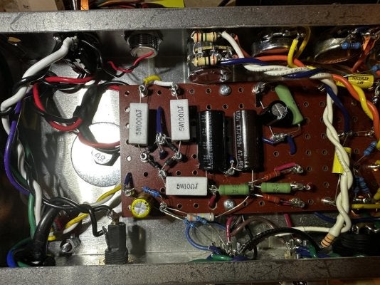
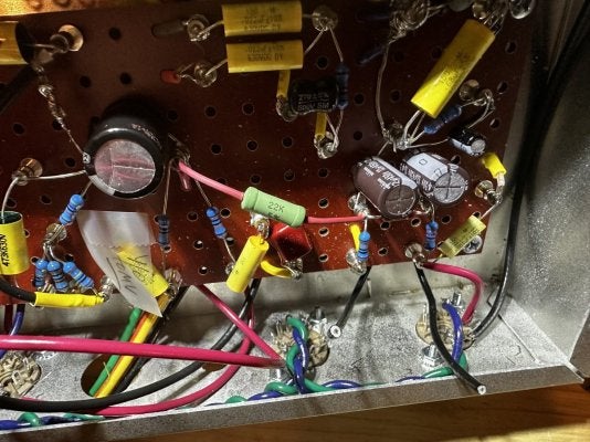
I fit an (almost) entire PS between to five lug terminals, and found the radials to be quite helpful to keep things compact. I put the first filter in the middle of the full-wave bridge rectifier (note: I was meticulous with shrink wrap and ensuring space between leads and components—you don’t want to short something).

Not the only way to skin a cat, but one way to, as an example:


IMG_3098.jpegIMG_3101.jpeg
 

furor_furor

TDPRI Member
Joined
Nov 22, 2024
Posts
83
Age
55
Location
yes
Hi all,

thanks for your feedback.
I am working on a schematic, but in essence it's just a 5f2a with a TB-tone stack (I might put a 25-50k pot meter at the back for variable mids, which might make the tone lift toggle obsolete, no?), adding trem from a vibrochamp, basically, and a reverb from the silverlake schematic.

The negative on the bridge is basically also what Rob Robinette has done on his micro amps. I considered a split bus on my 5E3, but I went for the updated version (single bus but the power section is somewhat separate before connecting to the main bus). Anyway, I'm happy to just use a single bus, or have some kind of star shape layout (i.e. a single lug close to the input but running separate wires from e.g. HT, pre-amp, input).
There will be a proper grounding connection from the mains.

I will try point-to-point, using terminal strips and direct connections where possible.
I already have my axial caps, but I added radials to my basket ^^ I can give it a try, but I have only 1.5" of 'headroom', iac =<2".
I have considered such a can or attaching them on the bottom, but I don't know if I have sufficient space.
Does the transformer interfere with the speaker if too close?

Thanks!
 

ievans

Tele-Meister
Joined
Jul 8, 2009
Posts
379
Age
50
Location
Sucka Free, CA
I like mounting radial caps horizontally across the terminal strips (and used some silicone to stabilize them). Each pair shares a ground lug, and the ground is isolated so I can tie it to a single point of my choosing.

1755213880380.png
 

furor_furor

TDPRI Member
Joined
Nov 22, 2024
Posts
83
Age
55
Location
yes
20250816_150710.jpg

A first version of the schematic for the basic amp. Tremolo and reverb not yet inserted. Some values still need to be added or changed.
The OT connection to a DPDT is probably not yet correctly drawn.

I'm wondering whether I would put the volume before or after the tone stack.

Should the tonestack lift interrupt the ground connection or should I bypass it before entering the tonestack? I.e. directly from the volume to the v1b grid.
Still wondering if i would add a potmeter for the mid control (need to be installed at the back then) or have a fixed resistor.

More to come, including calculations!
Thanks
 
Last edited:

2L man

Friend of Leo's
Joined
Nov 23, 2020
Posts
4,693
Age
65
Location
Finland
When there are two output jacks the switch is not needed! Switches also can be found to be set wrong much more than connect plugs!

When outputs have separate jacks increase versatily. You can connect same time 8 ohm speaker to 4 ohm output and 16 speaker to 8 output and OT impedance stay "nominal" and both speakers use equal powers!

Very versatile is when 4 output has two jacks, 8 output has two jacks and 16 has one jack. Then 8+8 or 16+16 or 8 +16 speakers/cabs are easy to connect.
 

Crowe Baaah

Tele-Holic
Gold Supporter
Joined
Aug 11, 2024
Posts
562
Age
44
Location
PA
When I was designing a similar amp, I took the approach that because I wasn't using a cathode follower before the tone stack, I wanted to minimize signal loss (the impedance does not match as well from a typical gain stage as it does from a cathode follower). So I chose to put volume knob after the tone stack (maybe it doesn't make a difference).

The reverse engineered schematics available online for Trainwreck amps follow a similar topology so I felt this was the way to go.

Also, on the tone stack lift, if you have space to put a 100kA mid pot in, you can get the extra tone shaping from the variable resistance but also can effectively bypass the stack at max resistance:
 
Last edited:
Top