1948 Gibson BR9 Amp Speaker Replacement and OUTPUT TRANSFORMER?!

  • Thread starter eugenedunn
  • Start date
  • This site may earn a commission from merchant affiliate links like Ebay, Amazon, and others.

eugenedunn

Friend of Leo's
Joined
Dec 18, 2006
Posts
2,707
Location
Sacramento
Fender_Woody_Gibson.jpg


Howdy gang,

I've been pretty busy lately tweakin' my family of itsy bitsy vibey vintage valve amps.... nothing really invasive, but stuff like tubes and speakers.


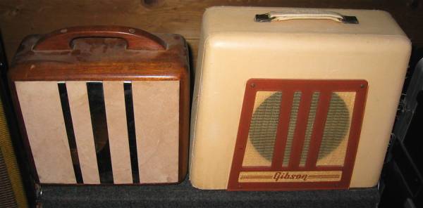
Put some nicer tubes into this 1948 Gibson BR9 that I've had for about 20 years. The original 4-ohm 8-inch field-coil speaker was reconed I'd say about 10 years ago. At any rate, seeing as field-coil speakers are weak to begin with, I was thinking about taking the original out and putting it away for safe keeping, but putting in the 3.2-ohm 8-inch original speaker I removed from my 79 champ.

That Champ's speaker is a permanent magnet type and probably beefier. I just thought I could use it for something cool rather than let it sit in a box.

So my big question is: If I remove the speaker from the Gibson, it has an attached small transformer.... the output transformer? If that's removed also, a regular permanent magnet type speaker won't work right?

Has anybody ever done this before and converted to a permanent magnet speaker? Or is this something you don't even want to contemplate for long?

At any rate, please educate me on this type of speaker set up.

Thanks so much everyone.......

Geno
 

6x47

Tele-Holic
Joined
Mar 28, 2007
Posts
804
Location
Northern ON
Replacing The Electromagnetic Dynamic Speaker With a PM Speaker

To replace the dynamic speaker with a pm (permanent magnet) speaker, the field coil that was serving as a filter choke must be replaced with a suitable substitute. The coil can be replaced with either a regular filter choke, which is mounted on the chassis and simply soldered in place of the now missing field coil, or a power resistor that matches the resistance of the field coil can be used. The use of a resistor will reduce the filtering of the B+ as a resistor has no inductance, so extra filter capacitance may have to be added to keep the hum within acceptable limits. Consideration must also be given to the power rating of the resistor. Wattage can be calculated by squaring the current flowing through the resistor, multiplied by the resistance.

Example: assume a 1500 ohm resistor used to replace a field coil has 70 milliamperes of B+ current flowing through it. Squaring the current, (.07 X .07 =.0049), multiplied by 1500 ohms = 7.35 watts. At least a 10 watt unit should be used, and 15 watts would be even better. Since this resistor will run rather warm it should be mounted so the heat generated will not affect other components.

With the field coil replaced by either a resistor or filter choke, a pm speaker can now be used to replace the dynamic one. If the output transformer is mounted on the dynamic speaker, it must be removed and either mounted on the replacement speaker or on the chassis and wired to the new speaker.

See diagram of electromagnetic dynamic field coil speaker with hum-bucking coil, a typical power supply circuit with speaker field coil used as filter choke, and diagrams showing the R.M.A speaker- plug wiring.

http://www.radioremembered.org/edspeaker.htm
 

eugenedunn

Friend of Leo's
Joined
Dec 18, 2006
Posts
2,707
Location
Sacramento
Thanks for the very complete answer to my question. That is awesome.

So it appears that if I was to convert to a permanent magnet speaker, I have to get a filter choke to take the place of the removed field coil.

Your instructions do specify how to calculate the value of a replacement resistor, but not what kind of filter choke to get. Are they pretty standard then? It sounds like using a resistor might be the cheap way out, but might be trial and error to get the right extra filter capacitor value to get rid of any hum induced by the resistor replacement scheme.

So any input on what kind of filter choke to use?

If it's easy to get one, I might just do this.
 

6x47

Tele-Holic
Joined
Mar 28, 2007
Posts
804
Location
Northern ON
I just reproduced the article http://www.radioremembered.org/edspeaker.htm

If you google this it would appear that most people opt to go with the 1.5K 10w resistor. There is a 1K listed on eBay right now. (link removed)
This value is also mentioned for a replacement.


If you play with google you will find a very good article complete with drawings.

I came across it when I decided to upgrade the speaker on my BR4 but I lost the article and link when my harddrive got messed up by a worm.
 

6x47

Tele-Holic
Joined
Mar 28, 2007
Posts
804
Location
Northern ON
If your amp is wired like this drawing http://www.schematicheaven.com/gibsonamps/br9.pdf the upgrade will be simple.

The 2 wires from the output transformer go to the new speaker (probably 4 ohms) and the resistor will go between the 10uF and 20uF filter caps.

Having said that, the Gibson schematics have a reputation of varying from the retail product and if the br9, like the br4, has 4 wires connected to the speaker frame and amp chassis via 6 pin connectors, it will take some time to trace out the wiring and try to relate it to the drawing.

Hopefully you'll get lucky.
 
Top